
A DC power supply boost circuit
The DC booster circuit operates on the principle of increasing the voltage from a lower voltage source to a higher voltage output. This is accomplished through the use of a step-up transformer, which consists of primary and secondary windings. The primary winding is connected to the input voltage source, while the secondary winding delivers the boosted voltage to the load.
In this design, the transformer’s winding ratio plays a crucial role in determining the output voltage. By adjusting the number of turns in the primary and secondary windings, the desired voltage level can be achieved. For example, if the primary winding has 10 turns and the secondary has 20 turns, the output voltage will be double the input voltage. This flexibility allows for customization based on the specific requirements of the application.
Furthermore, the circuit can be modified to function as a voltage doubler. In this configuration, the circuit is designed to produce an output voltage that is twice the input voltage. This is particularly useful in scenarios where higher voltage levels are required, such as in powering certain types of electronic devices or circuits that demand more voltage than what is available from the power source.
The voltage doubler or tripler configurations involve additional components, such as capacitors and diodes, which are used to store and redirect the voltage effectively. These components work together to ensure that the output voltage is stabilized and meets the necessary specifications for the intended application.
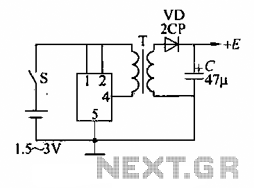
Overall, the DC booster circuit is a versatile solution for applications requiring increased voltage, with the capability to be tailored to meet specific voltage needs through adjustments in the transformer winding ratio and circuit configuration.DC booster circuit shown in Figure flooded. Which is a step-up transformer circuit diagram, step-up transformer T can receive a small transistor radios changed rattan change the winding ratio according to the desired voltage. Figure 2 b is a voltage doubler circuit, if desired, also be designed as pressure MG} 3, 4 times the pressure circuit.
Related Circuits
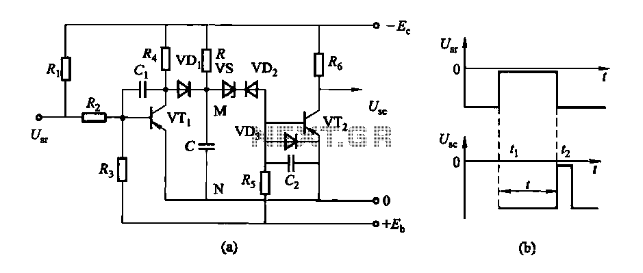
The circuit features a delay action with an instantaneous reset control mechanism. It is categorized into three types: a conducting pipe rechargeable delay circuit, a tube cut-off control rechargeable delay circuit, and a discharge-type delay circuit. In the conducting...
The following diagram is the schematic for a variable power supply that delivers an output voltage ranging from 0 to 28V at a current of 6/8 A. The component part list includes: R1 = 2.2 kΩ, 2.5 Watt; R2...
The power supply is based on the LM317 and LM337 variable 3-terminal regulators ICs, and while it is no powerhouse, it is quite satisfactory for testing most power amps, as long as there is no speaker connected. The circuit utilizes...
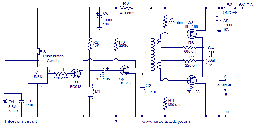
A straightforward intercom circuit designed using transistors. It does not require a changeover switch and can be used similarly to a telephone. This intercom circuit utilizes transistors to facilitate communication between two or more stations without the need for complex...
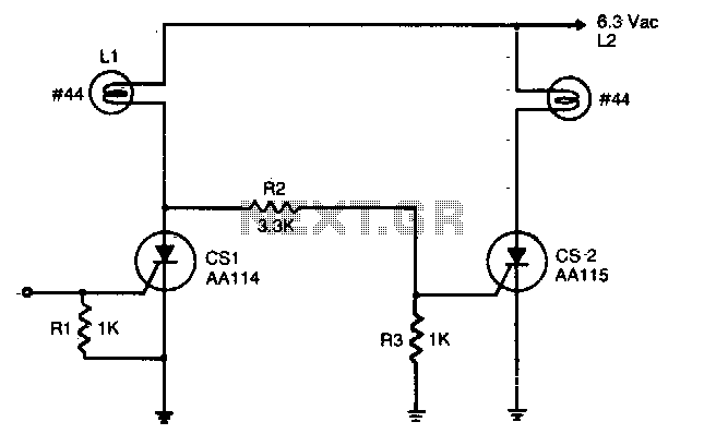
An input signal of less than 1 mA and 1V is required to switch on CS1. As long as this input signal is maintained, CS1 will conduct during each positive half-cycle of anode voltage, thereby energizing load L1 with...
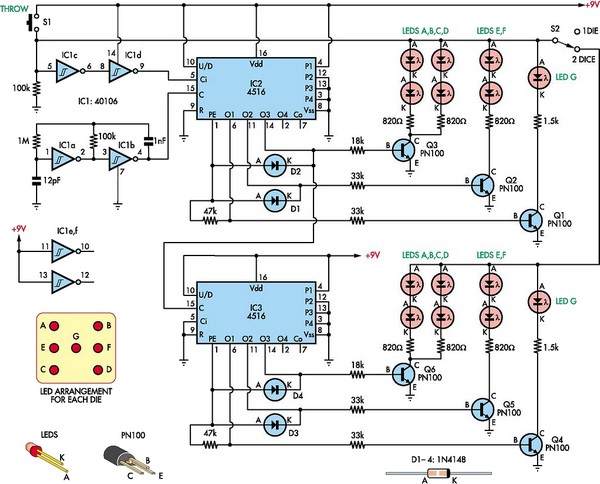
This circuit utilizes two 4516 integrated circuits (ICs) to simulate a game involving two dice. A switch is included to select whether one or two dice will be activated with each press. A 9-volt battery is sufficient for power...
Warning: include(partials/cookie-banner.php): Failed to open stream: Permission denied in /var/www/html/nextgr/view-circuit.php on line 713
Warning: include(): Failed opening 'partials/cookie-banner.php' for inclusion (include_path='.:/usr/share/php') in /var/www/html/nextgr/view-circuit.php on line 713