
Thermometer circuit with AD595
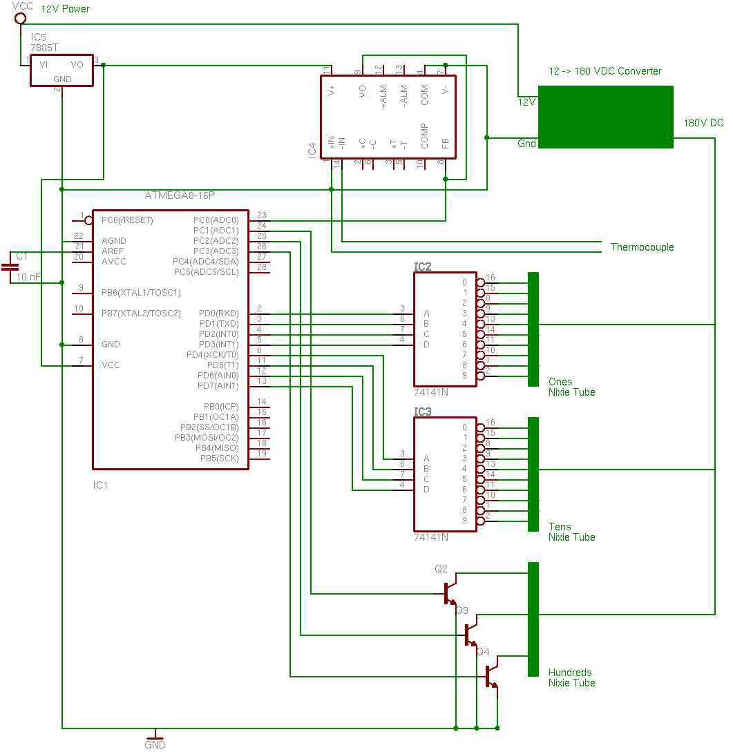
The circuit consists primarily of integrated circuits, which facilitates a streamlined assembly process on the circuit board, optimizing for soldering efficiency. The design utilizes a nixie tube for displaying temperature readings, specifically employing only three pins from the third nixie tube to represent the hundreds position. This decision conserves space and components, leading to the choice of using high-voltage transistors (MPSA42) in lieu of a 74141 integrated circuit. This approach is predicated on the assumption that the thermometer will not need to display temperatures exceeding 399 degrees, thus simplifying the design without compromising functionality for the intended range.
A critical component in the circuit is the AD595 thermocouple amplifier, designated as IC4. While alternative methods could achieve similar results with passive components such as resistors and custom programming, the AD595 was selected for its ease of integration and additional features that may be leveraged for future enhancements. The AD595 is notable for its ability to handle non-linearities inherent in thermocouple outputs, providing a straightforward formula to facilitate accurate temperature readings. The selection of this integrated circuit reflects a balance between immediate requirements and potential future applications, ensuring that the design remains versatile and adaptable.the entire circuit is comprised of integrated circuits. This makes for some easy organization when it goes to the circuit board for soldering. In addition, I used only 3 of the pins on the 3rd nixie tube for the hundreds position in the display. Since I was only using three, I decided to save a 74141 IC and just use a few high voltage transistors (MPSA42).
I figure the thermometer will very unlikely be in any situation where a temperature between 0 and 399 will ever need to be displayed, and if it is, the electronics will probably not work anyways. The other thing to point out here is IC4, the AD595 thermocouple amplifier. Again, here I could have easily done this without purchasing somewhat of a costly IC. A few resistors and a little more creative programming allows for pretty much the same result. However, at the time I hadn't really thought that through all the way and this seemed like an easy and quick solution. The AD595 also has many other features which in the future could be used to do some fun stuff with. Check out the spec page for details. The AD595 also provides a simple formula for dealing with non-linearities in the thermocouple. 🔗 External reference
Related Circuits
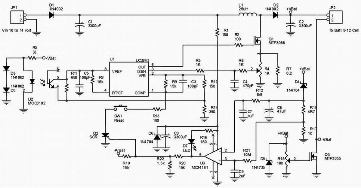
This is a NiMH battery charger using the IC LTC4060, which is powerful, effective, and efficient. The LTC4060 IC specializes in NiMH battery charging, ensuring safe operation with features such as battery temperature protection during charging. It includes a...
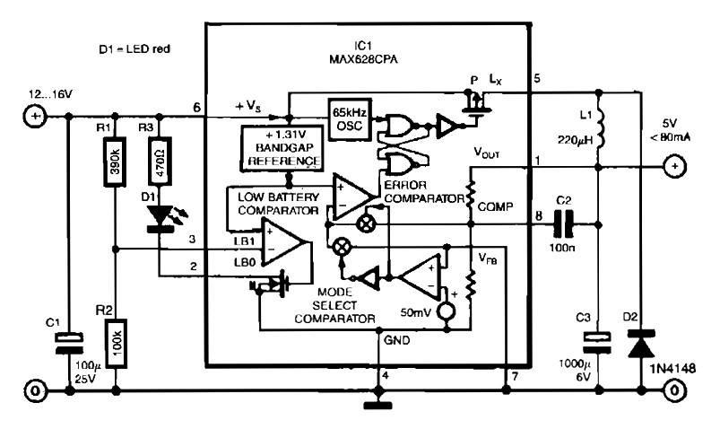
The circuit utilizes the MAX638CPA 5V CMOS Step Down Adjustable Switching Regulator IC, which converts an input voltage of 12 to 16 VDC into a stable 5VDC output. It requires only nine additional external components to complete the circuit....
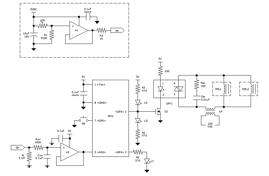
While discussing an all-linear automatic night light circuit, it was mentioned that an MCU-based Automatic Night Light Controller (ANLC) was being tested. The firmware has been tweaked since then. Recently, the sensor was installed outdoors and connected to control...
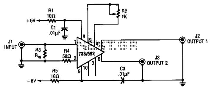
This circuit selects one of two channels using a logic signal. The unused channel is shorted out to minimize crosstalk. The bandwidth at -3 dB is approximately 8 MHz. It is recommended to buffer this circuit due to some...
The metronome circuit has been assembled multiple times without success. Two manufacturers of the 555 timer, ON Semiconductor and National Semiconductor, provide circuit designs that differ from the original. In their designs, pins 2, 6, and 7 are not...

The Tesla Coil will utilize a high voltage (HV) power source that outputs 9 kV at approximately 30 mA. The construction of the Tesla coil includes six glass bottles, table salt, oil, and aluminum foil for the capacitors. The...
Warning: include(partials/cookie-banner.php): Failed to open stream: Permission denied in /var/www/html/nextgr/view-circuit.php on line 713
Warning: include(): Failed opening 'partials/cookie-banner.php' for inclusion (include_path='.:/usr/share/php') in /var/www/html/nextgr/view-circuit.php on line 713