
Intelligent sensor signal processor configured MAX1463 precision pressure detection circuit
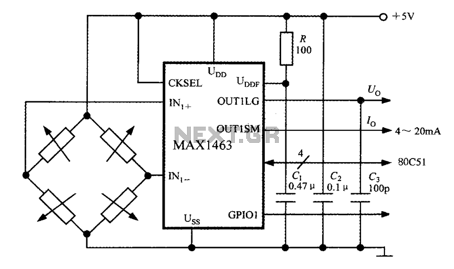
The MAX1463 precision pressure detection system integrates several critical components to ensure accurate pressure measurement and reliable operation. The bridge pressure sensor serves as the primary transducer, converting pressure into an electrical signal. The output voltage from the sensor is fed into the MAX1463 at the IN1+ and IN1- terminals, where it is conditioned for further processing.
The CPU plays a pivotal role in managing the system. It oversees the nonlinear calibration and temperature compensation processes, which are essential for maintaining measurement accuracy across varying environmental conditions. The A/D converter converts the conditioned analog signal into a digital format, which is then sent to the 80C51 microcontroller via a serial output interface. This microcontroller acts as the central processing unit, executing algorithms stored in flash memory to ensure precise linearization and compensation of the sensor signals.
The digital-to-analog converter (DAC) is responsible for generating an analog output voltage (Uo), which reflects the measured pressure and is displayed on a digital voltmeter. This output facilitates easy monitoring of pressure values in real-time.
In terms of system reliability, the GPI01 pin connected to the fault alarm system is crucial. It serves as a safeguard against potential faults, such as sensor lead disconnections or CPU errors during program execution. In such cases, the system activates a buzzer to alert users of the issue, ensuring prompt attention to any anomalies.
The internal clock oscillator of the MAX1463, set to 4MHz when the CKSEL pin is high, provides a stable timing reference for the CPU and ADC. This synchronization minimizes system noise, enhancing the overall performance and reliability of the pressure detection system. The architecture of this system reflects a careful design aimed at precision, reliability, and user safety in pressure measurement applications.Constituted by a circuit block diagram MAX1463 precision pressure detection system as shown in FIG. Bridge pressure sensor output voltage connected to the MAX1463 IN1 +, IN1- e nd. Under the control of CPU, the pressure signal sequentially through a nonlinear calibration and temperature compensation after A/D conversion from the serial output interface to 80C51 microcontroller; DAC also been converted to an analog output voltage Uo, sent to the digital voltmeter is showing measured pressure value. General-purpose digital I/O interface GPI01 pin is connected to a fault alarm, when overflow sensor lead open or CPU occurs during program execution, you can drive the buzzer alarm.
Linearization and temperature compensation of the sensor signals are stored by a user-defined algorithm done in flash by. CPU according to prescribed procedures to execute instructions stored in flash memory. When CKSEL termination high, MAX1463 selects the internal 4MHz clock oscillator. Since the CPU and operation of the ADC is fully synchronized, thus reducing the system noise.
Related Circuits

A simple audio watt meter circuit or an audio power or audio level meter circuit with diagram and schematics to measure amplifier audio output power in watts. The audio watt meter circuit is designed to measure the output power of...
This is a pressure sensor signal conditioning circuit. It is a simple and inexpensive circuit due to its small geometry and the use of a straightforward pressure sensor. The pressure sensor signal conditioning circuit is designed to convert the raw...
The Park Aid system utilizes three LEDs to indicate the distance of a bumper barrier through infrared operation, designed for indoor use. The circuit diagram includes the following components: R1 (10K 1/4W resistor), R2, R5, R6, R9 (1K 1/4W...
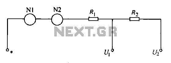
A voltmeter operates through a measuring mechanism in a specified circuit, utilizing a moving coil in series with additional resistance. The fixed coil is denoted as N1, while the moving coil is designated as N2. The additional resistances are...
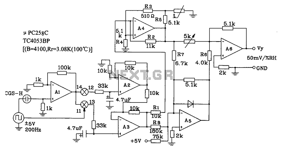
CGS-H ceramic humidity sensor constructed low humidity detection circuit diagram. The CGS-H ceramic humidity sensor is designed to detect low humidity levels within a specified range. This sensor operates on the principle of changes in capacitance that occur with variations...
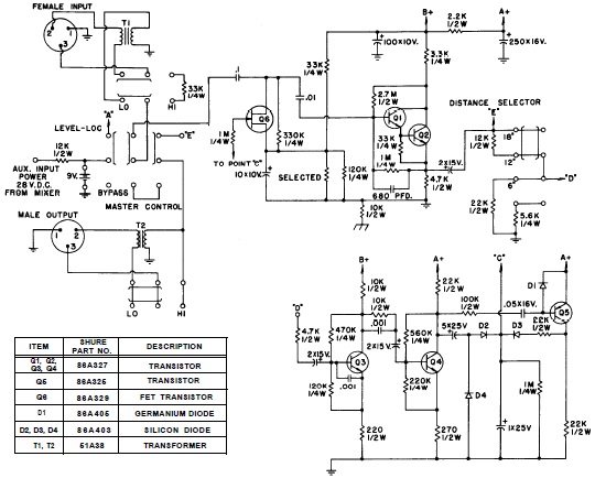
SHURE is an American corporation that manufactures consumer and professional audio electronics, including microphones, phonograph cartridges, and discussion systems. SHURE Incorporated is a well-established entity in the audio electronics industry, recognized for its innovative design and high-quality products. The company...
Warning: include(partials/cookie-banner.php): Failed to open stream: Permission denied in /var/www/html/nextgr/view-circuit.php on line 713
Warning: include(): Failed opening 'partials/cookie-banner.php' for inclusion (include_path='.:/usr/share/php') in /var/www/html/nextgr/view-circuit.php on line 713