
Electronic I CHING Detector
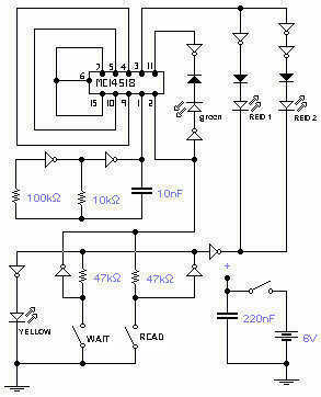
The electronic emulation of the I Ching circuit utilizes a systematic approach to replicate the traditional divination method through electronic means. The core of the circuit is a double counter IC, which serves as the primary mechanism for generating the hexagram lines based on randomization principles akin to coin tossing. The circuit design incorporates two MC14049B hex inverters that facilitate the manipulation of signal states, thereby enabling the accurate representation of the YIN (broken line) and YANG (solid line) characteristics of the hexagram.
The operational sequence begins with the user powering on the circuit, which activates a yellow LED to indicate readiness. The user then presses the "wait" button, during which the circuit enters a state of temporary suspension, allowing the counter to initialize while ensuring all other LEDs remain off. Following a brief pause, the user is prompted to press the "read" button, which triggers the display of the current state of the counter. The transition of the yellow LED to off signifies that the circuit is now actively displaying the YIN and YANG lines through the red LEDs.
The inclusion of a green LED adds further functionality by indicating a moving line, which is a critical aspect of the I Ching's interpretation. Each of the six readings corresponds to a line in the hexagram, and the user must repeat the wait and read process six times to complete the hexagram formation. This systematic approach mirrors the traditional method of generating hexagrams while providing an interactive electronic experience.
The circuit is designed to operate within a supply voltage range of 3 to 9 volts, offering flexibility in power source selection. The configuration of the components must be carefully arranged on a PCB to ensure proper signal flow and functionality, with the counter and inverters positioned to minimize interference and maximize reliability. The circuit's design not only serves as a modern interpretation of an ancient practice but also provides insight into the principles of random number generation and digital signal processing within electronic systems.This circuit is the electronic emulation of the I Ching, a form of divination originating in China. In the classical form, the response is obtained by the manipulation of 50 sticks or, more practically, by tossing 3 coins. The process must be repeated 6 times in order to complete what is called an hexagram. The various combinations given by the 6 readings are then read with the help of a book: the I Ching in fact or book of changes, used as a guide for the interpretation of the results.
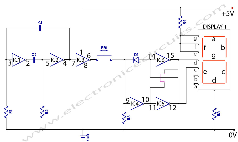
As the hexagrams look very much like a binary code, with additions and subtractions to go from one hexagram to the other, I thought that a hardware implementation could be feasible. The circuit reflects faithfully the chances of the I Ching: it is based on a counter which repeats a certain sequence, like a wheel. You may stop this rotation and read the counter status. In order to operate it you have to power it on and push "wait", the yellow LED will be on and all other LEDs will be off.
After a short while push "read", the yellow LED will go off and the other LEDs will be enabled and the information stored in the double counter will be displayed: either red 1 or red 2 will go on representing a YIN and YANG line respectively. The same line becomes a moving line if also the green LED is lit. This is the first line of the hexagram: repeat the process 6 times by pushing again "wait" and so on.
The whole circuit uses 3 ICs: one double counter and two hex inverters MC14049B. Supply voltage can be anything between 3 and 9V. 🔗 External reference
Related Circuits
The total cost for all components is significantly lower than that of a heavy-duty DPDT foot switch. As indicated on the previous page, suggested electronic switch circuits can be easily constructed, and their applications are justifiable. New mechanical switches...
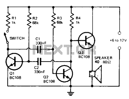
The circuit comprises a multivibrator (Q1 and Q2) and a low-power output stage (Q3). The speaker should have an impedance ranging from 40 to 80 ohms. To accommodate a low-impedance speaker, an output transformer should be connected from the...
This circuit will automatically switch on several mains-powered "slave" loads when a "master" load is turned on. For example, it will switch on the amplifier and CD player in a stereo system when the receiver is turned on. It...
This is an electronic coin toss circuit that utilizes a CD4049 integrated circuit (IC), which functions as a hex inverting buffer and TTL driver. The CD4049 contains six independent buffers that can be employed in various configurations, such as...
For hobbyists or professional electronic engineers engaged in various electronic experiments, troubleshooting, or testing, it is essential to provide a wide range of variable options. In electronic engineering, the ability to manipulate and measure a wide range of variables is...
The MSF transmitter transmits time data bit-by-bit over 60 seconds each minute by modulating a 60 kHz carrier frequency. It employs a continuous wave (CW) signal. Two bits are sent every second through variations in the duration and number...
Warning: include(partials/cookie-banner.php): Failed to open stream: Permission denied in /var/www/html/nextgr/view-circuit.php on line 713
Warning: include(): Failed opening 'partials/cookie-banner.php' for inclusion (include_path='.:/usr/share/php') in /var/www/html/nextgr/view-circuit.php on line 713