
switching

A normally open push-button switch activates a simple pulse conditioning circuit comprising Q1, a 1K ohm resistor, and a 0.4uF capacitor. The output of this circuit triggers pin 14 of a CMOS 4017 Counter, which is programmed to count from 1 to 4 by connecting pin 10 to pin 15. Each time the switch is pressed, the outputs of the 4017—pins 2, 3, 4, and 7—are activated sequentially to control one of the four switches of a CMOS 4066 Analog switch IC. This operation is characterized by speed and silence. To indicate which switch is active, an LED is connected to the outputs of the 4017 with current-limiting resistors (R1-R4) in series. These LEDs, labeled in sequential order from 1 to 4, also ensure that the switches remain off when a positive signal is not applied to their gates. Capacitors C1-C4 are optional but recommended for effective DC bypass and minimal noise. Additionally, the outputs can be combined to feed into a single input or maintained as separate outputs. If fewer than four switches are needed, the pins of the unused switches should be grounded.
The switch circuit should be housed in a robust enclosure large enough to accommodate a 9V battery, the main input and output plugs, as well as three 1/4" input and output receptacles for the effect circuits. Internal wiring will depend on the chosen configuration for output distribution; if combining outputs, a 10K resistor should be used for each output to isolate the effect circuits, followed by a 2 to 5uF capacitor to the main output plug. To manage the ON/OFF power, a stereo 1/4" plug should be used for the main input from the guitar, wired as depicted to the switch. The battery power can only be activated when the guitar plug is inserted into the switch input. It is crucial to connect all plug grounds together and to the negative side of the battery to ensure proper grounding of shielded cables, thereby preventing ground loop feedback noise and hum.
The circuit design integrates several critical components that work collaboratively to achieve the desired functionality. The use of the CMOS 4017 counter allows for efficient sequential switching, while the CMOS 4066 analog switch IC provides reliable control over the effect circuits. The LEDs serve not only as indicators but also as part of the circuit’s safety features, ensuring that switches are inactive when not in use. The enclosure design must prioritize durability and accessibility, allowing for easy replacements of components and maintenance. Proper grounding techniques are essential in minimizing noise and enhancing the overall performance of the circuit, making it suitable for various applications in audio processing and effect switching.The total dollars count for all parts is much smaller that the cost of an heavy duty DPDT foot switch. As seen on the previous page suggested electronic switch circuits can be made easily and I have found that their applications is justified.
New mechanical switches on the market like large game switches can be used as a foot switch, they are rugged enought for this application, large and attractive and their cost is very low. Developping further the basic electronic switch I have designed a circuit which by using a single push button foot switch will allow switching sequentially up to three effect circuits plus a by-pass. The Circuit below was designed for my son and after using it said to me " Dad you should patent this as there are none on the market except for those found on expensive computerized multiplexed board ".
He was enchanted with its performance, fast, noiseless, no signal loss and easy to use. As previously mentionned, a normally opened push button switch is used to activate a simple pulse preconditiong circuit made with Q1, 1K ohms resistor and a. 4uF capacitor. The output of this circuit trigger is connected to pin 14 of a CMOS 4017 Counter. As the counter is programmed to count from 1 to 4 by connecting pin 10 to pin 15, each time the switch is depressed, the output of the 4017, pins 2, 3, 4 and 7 are switched on sequentially to activate one of the four switches of a CMOS 4066 Analog switch IC.
This action is very fast and noiseless. See more about the CMOS4017 applications on pages 34 and 35 then press "BACK" to return to this page. To identify which switch is activated, an LED is connected to the 4017 outputs with a current limiting resistor, R1-R4, connected in series, In addition to identify the switches it insure that the switches are off when a positive signal is not applied to the switches gate.
These LEDs are labelled in their sequential order from 1 to 4 as shown on the schematic. The capacitors C1-C4 are shown as optional, but should be used for insurance of good DC by-pass and minum noise. Also as an option the outputs can be tied together as in the case to feed into one input or as seperate ouputs.
If you need less than the four switches, tie the unused switches associated pins to ground. and see page 34 for informations on the 4017 maximum count setting. Install the switch circuit into a sturdy enclosure that will be large enought to accomade a 9 Volts battery, the switch main input and output plugs in addition to three input and output 1/4" receptacles to accomodate three effect circuits as shown. Internal wiring will depend on your choice of distribution whether you will tie the outputs together, if so, use a 10K resistor for each output to isolate the effect circuits, followed by a 2 to 5uF capacitor to the main ouput plug.
To control the ON/OFF power, use a stereo 1/4" plug for the main input for the guitar and wire the voltage source as shown to the switch. As shown the power from the battery can only by switched ON when the guitar plug is inserted into the switch input plug.
Ground loop It is imperative that all plugs grounds be connected together and to the battery negative side to ensure good grounding of the shielded cables to prevent ground loop feed back noise and hum. 🔗 External reference
Related Circuits
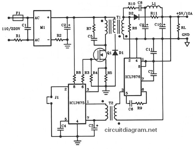
The following diagram illustrates the design of a 50W offline switching power supply circuit. This circuit is powered by a MOSFET, specifically the BUZ80A/IXTP4N8 for 220V AC input and the GE IRF823 for 110V AC input voltage. The output...
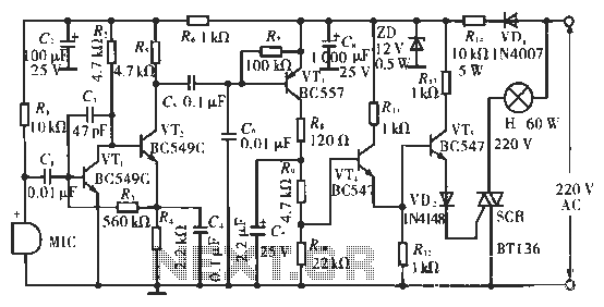
The circuit utilizes condenser microphones to detect sound and convert it into signal variations. This signal is then processed through directly coupled transistors VT1 and VT2, which form an amplification stage before being fed into a switching circuit. The...

The MIC5156 is a device that incorporates a current limiting function, allowing it to handle high output currents. It can operate with or without a switching regulator circuit. The S terminal is left vacant, and a 16V Zener diode...

The switching power supply provides 12 volts at a maximum of 10 amps, utilizing a discrete transistor regulator with an operational amplifier acting as a comparator in the feedback circuit. The schematic does not depict the front panel power-on...

This circuit comprises a 15V TOP224Y, 2A output DC switching power supply. It utilizes three integrated circuits: IC1 is a monolithic regulator (TOP224Y), IC2 is an optocoupler (NEC2501), and IC3 is a precision voltage reference (TL431). The TL431 (IC3)...
The ADP1864 is a compact, cost-effective, constant-frequency current-mode step-down DC-DC controller. It drives a P-channel MOSFET to regulate an output voltage as low as 0.8 V with ±2% accuracy, handling load currents up to 5 A from input voltages...