
Motorcycle electronic Gear Indicator

The main circuit is based on an AVR ATTINY25/45/85 microcontroller, which reads the signals of the two Hall sensors and the neutral switch and outputs the current gear number to a 7-segment LED indicator, through a 4026 counter/decoder. The source code is written in AVR-GCC (WinAVR) and can be programmed with the default fuses using an AVR programmer (default: ATTINY25 microcontroller and USBTiny programmer). Moreover, the constant TOP_GEAR 5 should be changed to 6 for six-gear motorbikes. The suggested implementation for the main circuit is a small size, double-sided PCB, with SMD packages for the microcontroller and the decoder ICs. The 7-segment LED is placed in a secondary PCB, connected vertically to the main one in a modular fashion. Two PCBs for different Kingbright LED footprints (red and blue) are also provided. In the current design, when the neutral switch is open (there is a gear on), there appears to be a very small current (< 0.5 mA) sinking through R3, due to the voltage difference between the neutral switch connection (TO_POWER-4) and the microcontroller. If the neutral indicator is of LED type (not a resistor bulb), there is a possibility that it stays dimmed, instead of being completely off. In that case, a small switching diode (1N4148) can nicely replace R3 (on the same PCB) in order to block this small incoming current when the neutral switch is open.
The circuit operates on a 12V power supply, which is typical for motorcycle applications. The Hall sensors are positioned to detect the magnetic field generated by the small magnet attached to the gear shift lever. The microcontroller continuously monitors the Hall sensor outputs to determine the current gear position based on the magnetic state changes. When the magnet's south pole approaches the Hall sensor, the microcontroller registers this as a gear change. The 7-segment display is driven by the CD4026, which decodes the binary output from the microcontroller into a visual representation of the gear number.
In addition to the primary function of displaying the gear, the device includes a self-test feature that activates upon power-up. This self-test ensures the integrity of the LED display by cycling through all digits, providing immediate feedback on the operational status of the indicator. The implementation of the EEPROM allows for persistent storage of the last gear displayed, ensuring that the user does not lose their place when the motorcycle is turned off.
The design also considers the potential issue of the neutral LED indicator remaining faintly lit when it should be off. By incorporating a diode in place of R3, this issue is effectively mitigated, ensuring that the LED behaves as expected under various operational conditions.
Overall, this universal gear indicator represents a practical solution for older motorcycles, enhancing functionality without the need for complex integrations with existing vehicle electronics. The modular design allows for easy installation and adaptability to different motorcycle models.This is a new design for a universal gear indicator that can be fitted to any motorcycle as an aftermarket accessory. Its main advantage is that its operation depends entirely on the gear shift lever movement, instead of connecting to speedometer and tachometer sensors (found in expensive commercial devices), which are rarely available in older motorcycles.
It consists of a main circuit including a 7?segment LED indicator, two Hall sensors that are attached to the motorcycle frame, and a small magnet placed on the gear shift lever. A successful circuit build will do a self-test when connected solely to 12V power (pins TO_POWER_1 and TO_POWER_2), by cycling through all digits on the 7-segment display (see video below). After the self-test, the current gear will be shown and can be changed by the shift lever movement. Note that a gear is changed when the magnet's south pole is drawn away from the sensor (north pole will not work).
Moreover, if a neutral gear is detected (from the neutral switch connected to TO_POWER_4), the display resets to zero (also acting as a self-calibrating feature if anything goes wrong). Finally, when the power is turned off, the last shown gear is stored in the MCU's flash EEPROM and restored when the device is turned on again.
The main circuit is based on an AVR ATTINY25/45/85 microcontroller, which reads the signals of the two Hall sensors and the neutral switch and outputs the current gear number to a 7?segment LED indicator, through a 4026 counter/decoder. The source code is written in AVR-GCC (WinAVR) and can be programmed with the default fuses using an AVR programmer (default : ATTINY25 microcontroller and USBTiny programmer).
Moreover, the constant TOP_GEAR 5 should be changed to 6 for six-gear motorbikes. The suggested implementation for the main circuit is a small size, double-sided PCB, with SMD packages for the microcontroller and the decoder ICs. The 7-segment LED is placed in a secondary PCB, connected vertically to the main one in a modular fashion (see pictures).
Two PCBs for different Kingbright LED footprints (red and blue) are also provided. In the current design, when the neutral switch is open (there is a gear on), there appears to be a very small current (< 0.5 mA) sinking through R3, due to the voltage difference between the neutral switch connection (TO_POWER-4) and the microcontroller. If the neutral indicator is of LED type (not a resistor bulb), there is a possibility that it stays dimmed, instead of being completely off.
In that case, a small switching diode (1N4148) can nicely replace R3 (on the same PCB) in order to block this small incoming current when the neutral switch is open, as shown in the figure below : For a better insight in the above issue, the following script can be imported in Paul Falstad's excellent circuit simulator (http://www.falstad.com/circuit) : $ 1 5.0E-6 10.20027730826997 62 5.0 50 R 160 112 160 64 0 0 40.0 5.0 0.0 0.0 0.5 R 480 112 480 64 0 0 40.0 12.0 0.0 0.0 0.5 r 160 112 160 192 0 10000.0 x 199 158 277 161 0 12 internal pullup x 93 41 245 47 0 24 Gear Indicator x 424 42 539 48 0 24 Motorcycle M 160 192 64 192 0 2.0 x 33 173 86 176 0 12 AVR Input w 160 192 160 272 0 w 160 272 224 272 0 162 480 112 480 176 1 2.1024259 1.0 0.0 0.0 r 480 176 480 272 0 470.0 w 320 272 480 272 0 d 480 272 480 352 1 0.805904783 x 373 316 459 319 0 12 protective diode s 480 352 608 352 0 1 false g 608 352 608 400 0 x 506 377 582 380 0 12 neutral switch x 232 249 314 255 0 24 1N4148 x 237 304 312 307 0 12 in place of R3 d 224 272 320 272 1 0.805904783 x 506 148 571 151 0 12 neutral LED 🔗 External reference
Related Circuits
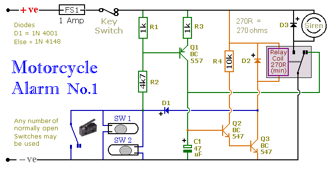
This circuit includes a timed output and an automatic reset feature. It can be manually operated using a key switch or a concealed switch. By incorporating an external relay, the circuit will automatically engage or immobilize the machine each...
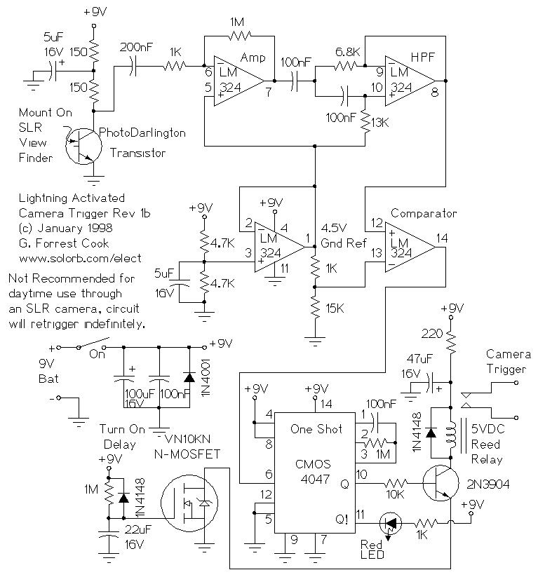
Basic information on the construction of various types of lasers from scratch, including topics such as home-built laser safety, setting up a home laser lab, sources of supplies and chemicals, vacuum systems, glass working, structural materials, power supplies, and...
This easy electronic buzzer circuit is built based on a timer that operates to generate frequency. The IC timer NE555 is used as an astable multivibrator operating at approximately 1 kHz, producing a sound when powered on. The sound...
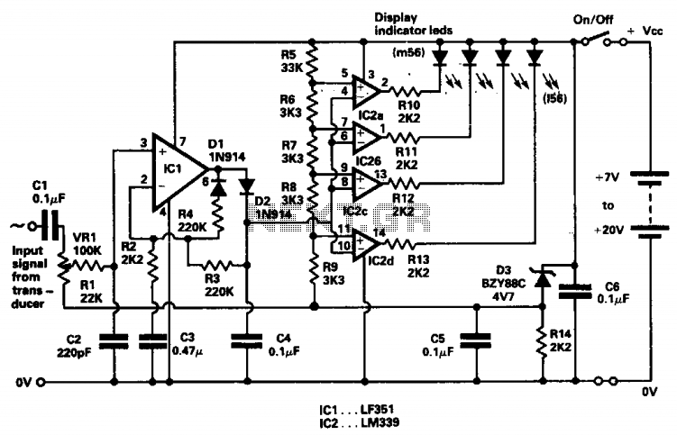
The indicator was designed to display the peak level of small AC signals from various transducers, including microphones, strain gauges, and photodiodes. The circuit responds to input signals within the audio frequency spectrum, specifically from 30 Hz to 20...
This is a circuit for alternative sources selection. It combines mechanical selection using a rotating switch S1, the electronic drive of the relays RL 1-10 and also the optical indication of the selection by the Display DSP1. The function...
Connect all connectors onto the flat cable using a small vice. This creates an instant male-male, male-female, and female-female serial adapter, along with a short extender cord. This tool is essential for those experimenting with serial ports. An additional...