
Electronic Siren with 2 transistors

The described circuit utilizes a PNP transistor (Q1) and an NPN transistor (Q2) to create an audio signal generator, functioning as a simple tone generator or siren. The operation begins when a voltage is applied to the base of Q1, triggering its conduction. This action simultaneously activates Q2 due to the direct coupling, leading to a decrease in the collector-emitter resistance of Q2 and allowing current to flow through the speaker's voice coil. This initial phase generates a sound as the speaker cone is drawn towards the magnet.
A 10nF capacitor plays a crucial role in this circuit. Initially uncharged, it connects to the collector of the PNP transistor, resulting in a simultaneous rise in voltage across both ends of the capacitor. This increased voltage further enhances the conduction of both transistors, creating a feedback loop that drives the transistors into saturation. As the capacitor charges through the base-emitter junction of Q1 and the collector-emitter junction of Q2, the charging current diminishes once the capacitor approaches full charge, leading to a gradual reduction in the conduction of Q1.
As Q1 begins to turn off, Q2 also starts to deactivate, causing the voltage at Q2's collector to drop. This drop in voltage affects the capacitor, causing it to discharge and subsequently turn off Q1 completely. The cessation of current through the speaker's voice coil results in the release of the cone, completing one cycle of sound generation.
Following this, the capacitor discharges through a 100kΩ resistor, reversing its charge and allowing the voltage at the base of Q1 to rise again, eventually reaching the threshold to turn Q1 back on. This cycle repeats, generating a continuous tone. Notably, if the touch plate is maintained, the tone's frequency increases, attributed to a higher voltage across the electrolytic capacitor leading to a quicker charging time of the 10nF capacitor.
This circuit exemplifies fundamental transistor operation and feedback mechanisms, serving as a foundational project for understanding electronic components and their interactions. Future explorations in electronics can build upon this understanding, facilitating deeper insights into circuit design and functionality.This project is built on the third section of the PC board, identified by "SIREN" and "Project 5." You will notice the similarity between this circuit and the LED FLASHER circuit from project 2. The only differences are the LED has been removed and the 22R resistor has been replaced by a mini speaker.
Since Q1 is directly coupled to the second transistor, Q2 turns on too. When Q2 turns on, the resistance between its collector and emitter reduces and allows current to flow. This causes current to flow in the voice coil of the speaker and pulls the cone towards the magnet. This is the first half of the cycle for the speaker. Also connected to the collector of the PNP transistor is one end of a 10n capacitor and when one lead of the capacitor rises, the other side rises too. (This is because it is uncharged at the moment). This has the effect of turning on both Q1 and Q2 even harder. This action runs around the circuit until both transistors are turned on fully. At this point the 10n capacitor begins to charge via the base-emitter junction of Q1 and the collector-emitter junction of Q2.
When the capacitor becomes nearly charged, the charging current reduces and it cannot keep Q1 turned on as much and it begins to turn off slightly. This begins to turn off Q2 and the voltage on the collector of Q2 falls. The 10n capacitor is connected to this and both ends begin to fall and turn off Q1. This action turns both transistors off and the voltage on the base of Q1 is below the negative rail (as explained in Project 2).
Current through the voice coil of the speaker ceases and the cone is released. This completes the cycle for the speaker and it's the action of pulling the cone towards the magnet and releasing it that produces the tone. The charge on the capacitor is now cancelled by the current from the 100k resistor and it begins to charge in the opposite direction so that the voltage on the base of Q1 rises to .6v.
At this point the NPN transistor turns on again and the cycle repeats. If the touch plate is kept touched, the tone from the circuit gradually rises as the time taken to charge the capacitor at the end of the cycle will be shortened. This is due to a higher voltage being present on the electrolytic and thus a higher current will flow through the 100k resistor to charge the capacitor faster.
Most of the explanations of how the circuits work have opened up more questions than they answered. This is only a commencement book and future books will elaborate on the operation of the circuits in more detail. Even if you have only learnt the resistor colour code and got the projects to work, you will have achieved all this book has intended to get across.
Furthermore, if you like what you have learnt, electronics will be buzz and a very rewarding hobby. Look out for the next books in the series. 🔗 External reference
Related Circuits
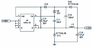
The following file is an application note describing the two stages of an electronic ballast for a 250 W HID metal halide lamp. The components include. The application note outlines a two-stage electronic ballast designed specifically for a 250 W...
The circuit consists of two multivibrators. The first multivibrator controls the speed of the transition from 'hee' to 'haw' and operates at a low frequency. The circuit features two distinct multivibrator configurations, which can be identified as an astable multivibrator...
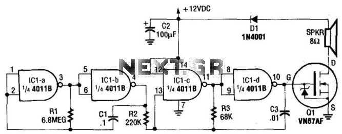
This circuit utilizes a CMOS chip and a VMOS FET amplifier to achieve 6 W of audio output. With a +24 Vdc power supply, it can generate up to 18 W of audio. IC1A and IC1B function as a...
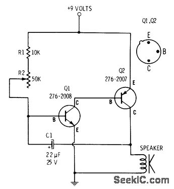
R2 controls the charging speed of capacitor C1. At a specific charge level, C1 triggers transistors Q1 and Q2, which release a 9-volt pulse. This pulse generates a clicking sound. The discharge process of the capacitor involves it charging...
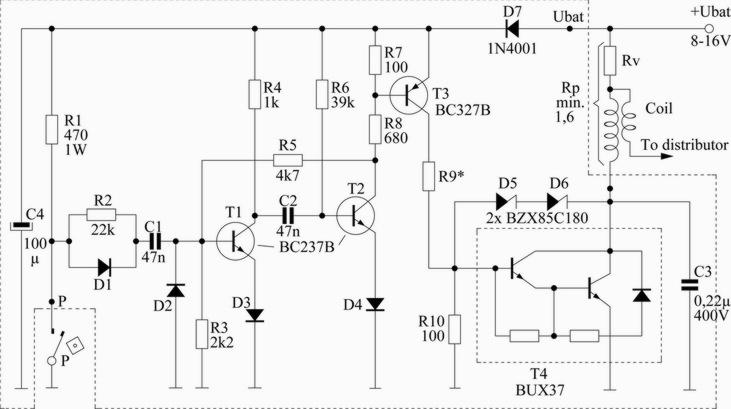
This scheme is designed for a four-cylinder engine. It aims to reduce fuel consumption, increase speed slightly, and minimize the need for frequent access to the distributor cap for contact button replacement, thereby saving costs. Transistors T1 and T2...
One integrated circuit (IC) two-tone siren. It produces a double-tone police sound and a single-tone old ambulance sound. Circuit diagram components include R1 and R3, which are 470K ohm 1/4 watt resistors, and R2, which is a 680K ohm...