
how to make electronic siren circuit
The described circuit functions as an oscillator that generates a sound resembling a police siren through a series of charging and discharging cycles involving capacitors and transistors. The primary components include the BC108B and 2N3702 transistors, which work in tandem to control the sound output based on the voltage changes across the capacitors.
Initially, when the circuit is powered, the 10µF capacitor is fully discharged, and both transistors are in an off state, preventing any current flow to the speaker. Activation of the push button switch initiates the charging of the 10µF capacitor through the 22kΩ resistor, causing a gradual increase in voltage at the base of the BC108B transistor. This slow turn-on characteristic is crucial for creating the desired sound modulation.
Once the switch is released, the discharge path for the 10µF capacitor through the 100kΩ and 47kΩ resistors allows the BC108B transistor to turn off gradually, creating a fading sound effect. The rapid activation of the 2N3702 transistor, triggered by the falling collector voltage of the BC108B, introduces a feedback loop that enhances the oscillation effect. The 22nF capacitor plays a critical role in this feedback mechanism, charging quickly and affecting the base voltage of the BC108B, thus controlling the timing of the sound oscillation.
The discharge of the 22nF capacitor through the various resistors and the speaker creates the audible sound. The time constant associated with the discharge determines the frequency of the oscillation, which can be adjusted by changing the resistor values or capacitor sizes. The overall design allows for flexibility in sound output, enabling the user to modify component values for different sound effects, thereby enhancing the versatility of the circuit.The sound produced imitates the rise and fall of an American police siren. When first switched on the 10u capacitors is discharged and both transistors are off. When the push button switch is pressed to 10u capacitor will charge via the 22k resistor. This voltage is applied to the base of the BC108B which will turn on slowly. When the switch is re leased the capacitor will discharge via the 100k and 47k base resistors and the transistor will slowly turn off. The change in voltage alters the frequency of the siren. The oscillator action is more difficult to work out. As the BC108B transistor switches on its collector voltage falls and so the 2N3702 transistor is switched on.
This happens very quickly ( less than 1us). The 22n capacitor will charge very quickly as well. As this capacitor is connected between the collector of the 2N3702 and the base of the BC108B, it soon reaches almost full supply voltage. The charging current for the capacitor is then much reduced and the collector emitter voltage of the 2N3072 is therefore increased; the collector potential will fall.
This change in voltage is passed through the 22n capacitor to the base of the BC108B causing it to come out of saturation slightly. As this happens its collector voltage will rise and turn off the 2N3072 transistor more. This continues until both transistors are off. The 22n capacitor will then discharge via the 100k, 22k resistor, the closed push button switch, 9V battery, the speaker and 56 ohm resistor.
The discharge time takes around 5-6msec. As soon as the 22n capacitor is discharged, the BC108B transistor will switch on again and the cycle repeats. The difference in voltage at the collector of the BC108B (caused by the charging 10u capacitor) causes the tone of the siren to change.
As the 10u capacitor is charged, the tone of the siren will rise, and as it is discharged, it will fall. A 64 ohm loudspeaker may be used in place of the 8 ohm and 56 resistor, and the values of components may be altered to produce different sound effects.
🔗 External reference
Related Circuits
The figure illustrates a schematic circuit of a UV sensor. When voltage is applied between the cathode and anode, and UV radiation passes through the quartz glass tube on the cathode's optical surface, the cathode material, which is coated...
This time, we will share information about Yo3dac's homebrew RF circuit design ideas, including the latest updates from Onmilwiki. Yo3dac is known for innovative approaches in the realm of radio frequency (RF) circuit design, particularly within the homebrew community. The...
A highly beneficial project involving a crystal tester circuit, also known as an xtal tester circuit, constructed with only a few components. The circuit forms an oscillator that will only oscillate if the crystal under test is functioning properly....
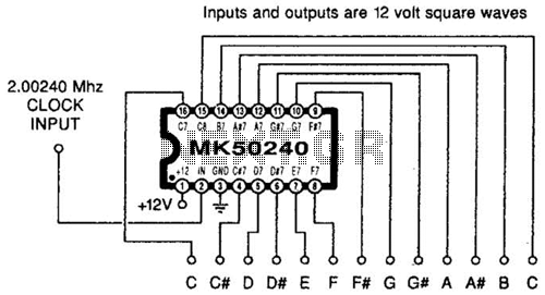
Using an MK50240, this circuit generates 12 top octave tones. The input and output lines can be separated using a binary divider IC to achieve the lower notes. Inputs and outputs are 12-volt square waves. The MK50240 is a specialized...
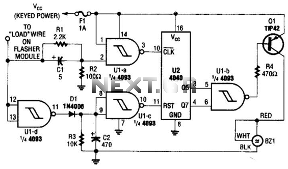
This circuit counts the flashes of turn signals. After approximately 70 flashes, a chime sounds to remind the driver to deactivate the turn signal. The period can be altered by using different taps on U2 if desired. BZ1 serves...
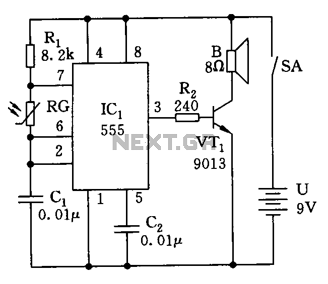
The electronic circuit simulates bird sounds under varying lighting conditions, particularly influenced by neon light irradiation, resulting in fluctuating and changing tones. The sound produced is continuously variable. The schematic of this circuit is provided. The described electronic circuit utilizes...