
Electronic potentiometer circuit composed of digital circuits
The digital integrated circuit described is designed for applications that require precise control over counting and switching operations, effectively integrating multiple functions into a single unit. The architecture leverages a combination of digital logic elements and analog components to achieve its objectives. The Schmitt trigger and NAND gates provide robust control signals, ensuring stable operation in various conditions. The use of presettable counters allows for flexible counting sequences, making the circuit adaptable for different operational needs.
The analog electronic switch (CD4067) plays a crucial role in routing signals through the circuit, enabling the selection of different input channels based on the control logic. This feature is particularly beneficial in applications that require the multiplexing of signals or the selective processing of multiple analog inputs. The resistor network complements the analog switch, providing the necessary impedance matching and signal conditioning to ensure optimal performance.
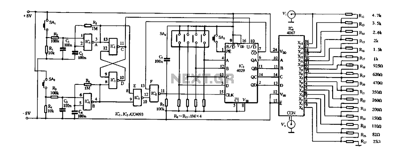
In summary, this digital integrated circuit exemplifies a sophisticated approach to managing and manipulating both digital and analog signals, making it suitable for various electronic applications that demand precision and flexibility in control mechanisms. The careful integration of components facilitates a streamlined design that enhances functionality while minimizing complexity.Figure 4-14 is a digital integrated circuit consisting of 16 preset potentiometers Siniperca electronic circuits. It consists of three parts: input into the controller. Presett able counter, analog electronic switch and resistor network. Assisted by a push-button switch and the controller Schmitt trigger four two-input NAND gate CD4093 composition. By adding to the counter to control the input, counting down switching pulse counting and addition and subtraction states.
Wherein ICIA, ICIB composition subtraction count the number of input NAND gate. Iclc.rq Hu lying grate RS flip-flop, whose output controls the down counting of the counter IC3 state transition when it outputs a high level, IC3 for counting; low output, IC3 for counting down. IC2E to the non-inverter, IC2F counting bit full control gate when the counter reaches the preset number or the full bit, IC3 output full bit (binary) signal IC2F closed to stop counting pulses input o can be preset count din.
BCD can be preset by the reversible counting ICCDt029 preset number and BCD switch composition for receiving add, subtract and count pulse input preset number b When the count full bit full controller output to the input signal. Counter after receiving the count pulse t by adding, after the down output BCD code. U/D conversion is down counting state control terminal, a high level, the counter for counting; low, the counter for counting down port analog electronic switch and resistor network.
By a single 16-channel analog switches CI, CD4067 16 and resistor networks.
Related Circuits
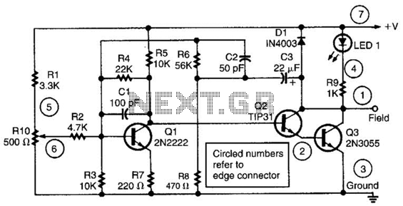
This alternator regulator utilizes a 3-transistor DC amplifier and is designed for a pulled-up field system, where one side of the alternator field returns to the +12V supply, and the other end is pulled toward ground. The circuit monitors...
The Colpitts oscillator has been redrawn for clarity. The inductor (L) is approximately 1.5 µH with 19 turns wound on a T50-6 core (yellow). The capacitor (C6) value has been determined experimentally, with a combination of 69 pF (using...
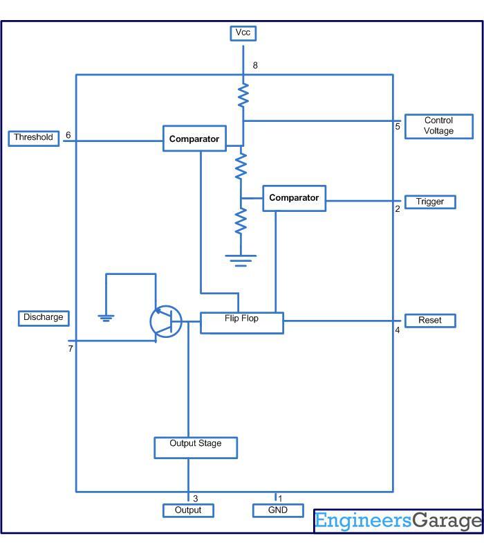
This circuit-based project demonstrates the operation of a 555 timer in astable mode to generate pulses with a time period of 0.5 seconds. These pulses can be utilized in various applications, such as blinking an LED or creating decorative...
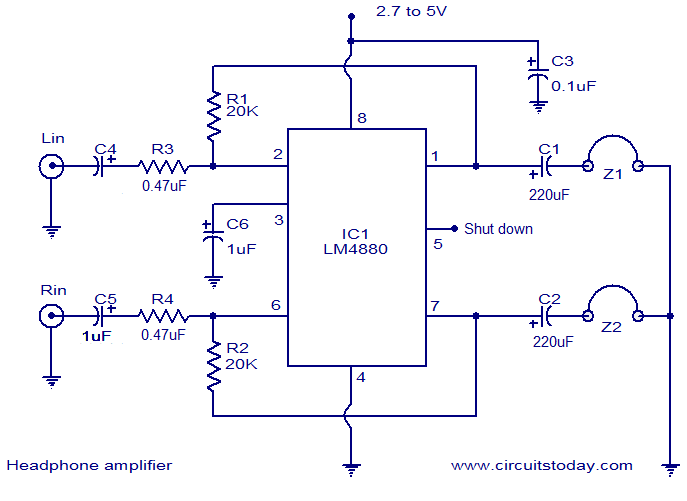
The LM4880 is a high-fidelity dual audio amplifier integrated circuit (IC) from National Semiconductors. This IC is specifically designed to deliver high-quality audio output with a minimal number of external components. The LM4880 can provide 250mW per channel into...
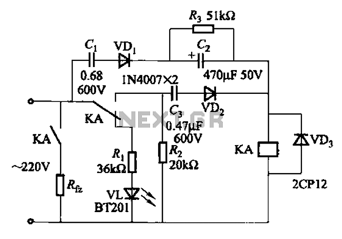
The AC power supply voltage is normal, and a relay is connected to the load (Rfz) circuit. In the event of a load short-circuit failure, the voltage across relay KA drops rapidly, causing KA to release and disconnect the...
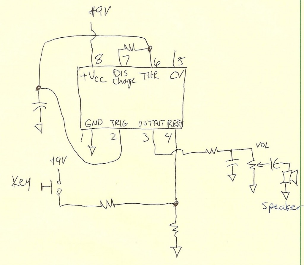
A code practice oscillator was built some time ago, and there is a vague recollection of the project. It featured a straight key that plugged directly into the key jack. Upon opening the device, a circuit board populated with...
Warning: include(partials/cookie-banner.php): Failed to open stream: Permission denied in /var/www/html/nextgr/view-circuit.php on line 713
Warning: include(): Failed opening 'partials/cookie-banner.php' for inclusion (include_path='.:/usr/share/php') in /var/www/html/nextgr/view-circuit.php on line 713