
Electronic Projects
The described circuit design focuses on a bit serial interface that utilizes a series of shift registers for data transmission. The choice of using an RJ11-6 connector facilitates easy connectivity with standard wiring, while the option of a four-wire version simplifies the setup for specific output applications. The dual-functionality of the strobe line enhances the efficiency of data handling, allowing for both output latching and input clocking.
The implementation of the H bridge configuration using high-capacity MOSFETs is critical for driving actuators that require significant current, ensuring reliable operation without thermal issues. The feedback mechanism through the exclusive OR gate not only allows for precise control of actuator movement but also enables the system to respond dynamically to the operational state of the actuators.
Overall, this circuit design exemplifies a robust solution for driving actuators in applications such as heliostats, where precision and reliability are paramount. The integration of feedback and control mechanisms ensures that the system can effectively manage the positioning of components, accommodating the demands of varying operational conditions.This program includes circuit design cad, simulation, and auto routing PC layout. I also use PSPICE at Unisys which has more capabilities but costs 6 times as much and needs to be renewed yearly. With these requirements in mind, and some others, I decided on a variation of National Semiconductors "Micro Wire"(TM).
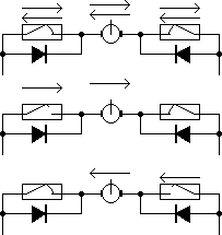
In general this is called a "bit serial" interface. The interface is composed of shift registers connected in series. Each port is in a chain. Data bits are sent down the chain through the shift registers for output. Input data bits are similarly sent down the chain to be inputted into the computer. My standard bit serial I/O consists of 6 wires. The wires for the standard version use an RJ11-6 6 conductor flat telephone type cable. I also have a simplified 4 wire version. This 4 wire version is predominantly used for output devices only. Pins 5 and 6 are not used. This version eliminates the data input channel and has no self powering capability. RJ11-6 Interface Data Input RJ11-6 Printer Port Adapter RJ11-6 Loop Through Connector. View from the Cable side View from the Cable side When choosing or building the cables that connect the computer and I/O boards together make sure they are the strait through type. In other words the cable has NOTWISTS in it. Terminator Bring the strobe line high and then low. The strobe line does double duty. It latches the output data into the output registers and drivers. It also clocks input data into the input shift registers that will be shifted in later. The first input bit is already present on the computer serial data bit input line. I needed to drive satellite dish type actuators for positioning components of my heliostats. I decided to design the interface such that it drives the most common, read cheap, types of these actuators.
These generally have either limit switches or overrun clutches to prevent damage to the drive train. Another trait is the use of a single counter switch. The satellite actuators can draw upwards of 15 Amps when in overrun. This takes a robust transistor. I have chosen 30 Amp P and N channel power MOSFETs in a true high voltage CMOS H bridge configuration. The implementation can drive 4 actuators continuously without overheating, not even warm, not even in hot weather.
The driver consists of an "exclusive or" gate driving the bridge. One input is from the computer software and the other is from the feedback actuator read switch. The job of the exclusive or gate is to apply power to the actuator motor driver until the condition of the feedback switch is the same as the movement bit from the computer. This process allows the computer to move the actuator in small single steps. The direction the actuator travels is determined by enabling pairs of transistors in the H bridge. One pair for movement outward and the other pair for movement inward. 🔗 External reference
Related Circuits
There are numerous LED flasher projects available on the internet, some of which are designed for low current consumption. However, the requirement was for an extremely small flasher suitable for geocaching that could last at least one year using...
Figure 1-1 illustrates a general-purpose timer capable of timing intervals ranging from 5 minutes to 18 hours. The timing cycle can be adjusted to span from 5 minutes to 20 hours, with a maximum control time of 18 hours....
This humidity detector circuit diagram is straightforward and utilizes a limited number of components. It can be employed to activate electronic devices when the detector identifies a specific humidity level. The sensor is made from two copper pieces positioned...

When a couple moved into their small apartment in San Francisco, they wanted to create a compact liquor cabinet and wine rack. After a visit to IKEA, they acquired a bookshelf that could be easily transformed into a stylish...
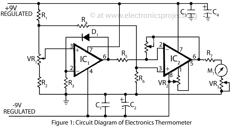
A clinical thermometer is typically used by doctors due to its complex reading mechanism. This circuit represents an electronic thermometer designed to measure a wide temperature range from -200°C to 1250°C. This single circuit electronic thermometer is capable of...
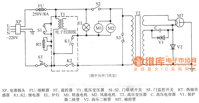
XP power plug, FU fuse, ST temperature control, T1 low-voltage transformers, S1, S2 door interlock switch, S3 threshold control switch, RT thermal sensor, K1, K2 relay, EL furnace light, M1 wheel motor, M2 fan motor, T2 high-voltage transformer, C...