
Electronics & Arduino
The circuit employs a simple microcontroller setup to manage the LED flashing. The code includes necessary libraries for sleep and watchdog timer functions. The LED is connected to pin 4 of the ATtiny85, and the program initializes the pin as an output. The main loop checks for a watchdog timeout, which triggers the LED to flash for a brief duration. Power conservation is achieved by setting the LED pin to input during sleep mode, minimizing current draw.
In addition to the flasher, a design involving a photoresistor (LDR) and a transistor is described. The LDR has a resistance of approximately 100kΩ in the dark and decreases when illuminated, affecting the voltage divider formed with resistors R1 and R2. This setup allows for the control of an LED strip based on ambient light levels. The circuit can be configured to either turn the LED on in light or dark conditions by swapping the positions of R1 and R2.
Another circuit design allows for an LED to be activated by touching two metallic elements, utilizing a BC517 transistor to amplify the weak current from the human body. The circuit can be expanded to control multiple LEDs by adding more transistors.
The final design focuses on creating a modular RGB LED lamp using an Arduino Mini Pro. The compact board is chosen for its low power consumption and compatibility with various Arduino projects. The RGB LED strips are powered at 12V, with each color channel controlled by PWM signals from the Arduino through BC337 transistors. The design incorporates potentiometers for brightness adjustment and a switch to select different lighting modes.
The overall circuit designs emphasize efficiency and modularity, aiming to provide a versatile lighting solution that can adapt to various needs while maintaining low power consumption. The implementation of PWM control allows for precise brightness modulation and color mixing, enhancing the functionality of the LED systems.On the internet there are so many Led Flasher`s projects, some even with low current consumption, but what I needed was a flasher to be used for geocaching, extremely small and that could last at least one year with a button battery. I started so a little experiments with the ATtiny85 low power modes using the sketch of insidegadgets, achieving a
power consumption of about 4. 5uA in standby and of about 3mA during the led flash that occurs every 4 seconds and lasts for about 30ms. /* Ultra Low Power Led Flasher with AtTiny85 @ 1Mhz by Luca Soltoggio 06/01/2014 */ #include
The operation is very simple: the photoresistor (LDR) has a value of about 100k © in the dark and when this is illuminated the resistance decreases and the voltage divider between R1 and R2, means that the gate of Q1 goes below the threshold level (between 2V and 4V) turning off the the Led Strip. With R1 I can set sensitivity, while reversing R1 and R2, I reverse the operation (it turns on with light and turn off with the dark).
The basic design published here simply allows you to turn on an LED by touching or immersing in water two metallic elements (cables, plates or whatever), but cloning the circuit and putting more transistors and more LEDs, we can get a gauge with 2, 3, 4 or 30 sectors. The operation is quite trivial: by touching the two contacts of the sensor SENS with hands for example, the weak current flowing through the body is sufficient to excite the transistor via the resistor R1 which serves as protection if we join directly the two contacts.
The BC517 is able to amplify this current approximately 30, 000 times, for which a current of 10 uA, is able to slide up to 300 mA through the transistor. The resistor R2 serves to prevent accidental starting by grounding the base of the transistor, while R3 is simply the resistor to limit the current flowing through the LED.
Schema corrected: obviously one of the two leads did not go to mass but on the positive I apologize for the mistake and thanx who rightly corrected me with his comments. Nothing to do. We have to consider LED strips as if they were bulbs or motors at 12V: they do not require special drivers to be controlled, but we simply have to feed them with a proper voltage (usually just 12V).
This is because LED strips are not simple LED, but within them ther is a circuit of series-parallel LED equipped with suitable resistances, and are then handled as a normal 12V equipment. One of the things that attracted me the most when I first heard of Arduino, was light, and in particular I have always dreamed of achieving an LED lamp RGB.
First of all, I did not find complete projects on the net There is something, but, in my opinion, with bad algorithms, with little explanation or with complicated methods. I wanted something that had a powerful enough light, without too much heat. I wanted something that had a chance to choose the color and not a simple color cycler. I wanted something that would serve also as a standard lamp. And finally, I wanted something that was modular and upgradeable in the future. After these reflections, I began to study the hardware first. I did not want to use the Arduino UNO because it seemed too big for my project. So I decided (and this could open up a huge parentheses) to use a board not so common, but in my opinion awesome (so much that I bought 4 or 5 piece): The Arduino Mini Pro.
It a very small board (18mm x 33mm), 100% compatible with Arduino Dumilanove, and low power consumption. It is available in four versions: with Atmega328 or with ATmega168, both with 3. 3V or 5V. So I opted in this project for the 5V version with ATmega168. In short it is a very economic solution (it costs about half of the Arduino UNO), very compact and beautiful to see.
I then thought of using the useful LED RGB strips, which offer many advantages over using 1W or 3W power LEDs: they do not heat up, they are powered with 12V and they offer a power up to 13-14W per meter. Each channel can be powered by a PWM output of the Arduino using a simple transistor (in my case I used the BC337, but for higher power you can use other transistor, or even the MOSFET).
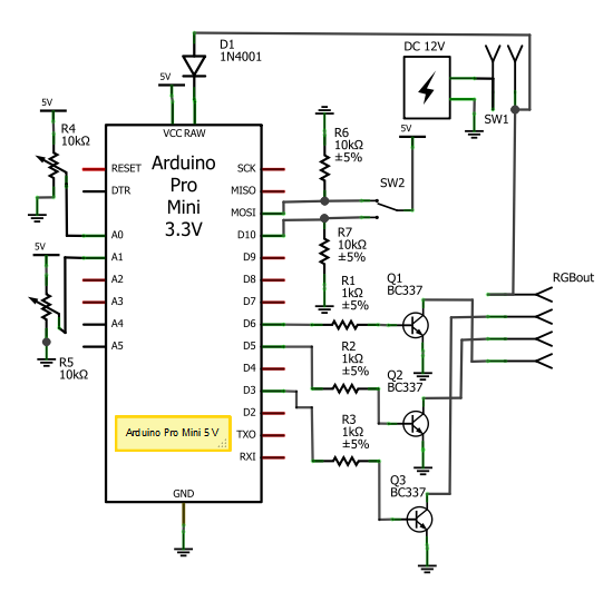
I then proceeded to build a kind of shield for my board. Practically I made a circuit in which the Arduino Pro Mini would fit with strip connectors and with the ability to be removed to upgrade the firmware. Everything has been designed with Fritzing and built by Fritzing Fab. In any case, the operation principle is as follows: The two 10k potentiometers connected between +5 V and ground, are the two analog inputs that allow to adjust the brightness and other parameters set by the software.
The 3-position switch SW2 allows you to select three different functions for the lamp. The digital outputs 3, 5, 6 go through a resistor to drive the 3 BC337 transistors that will give negative voltage to the 3 channels (R, G, B) of the LED strip. The common positive goes to +12 V, while the Arduino is powered by RAW port (input from 7V to 13V) via a diode that in addition to providing reverse polarity protection, slightly lowers the voltage.
SW1 is simply the bridge where will be connected a standard power switch. Once soldered the components, connectors, potentiometers, mounted the circuit, encapsulated the Arduino board, and assembled it all in a electrician box, the result is as in the following picture: For the top, I used about 70cm of RGB led strip, for a total power of about 10W. To fit the whole strip I rolled it around the support of a 50 CD-R set . I cut with a utility knife and I glued all with spacers on the box. I then glued with hot glue the wrapping strip led In short, the job is a little rough but the end result is as follows: The glass you see on the desk, is the final piece: the glass cover of a IKEA lamp, properly cut by a local glazier, so that it remains empty on both sides.
This coverage will finally resting on the box and glued, obtaining the following results: /* RGB Led Lamp 1. 0a by Luca Soltoggio 15/03/2012 */ int rpin = 3; // red pin int gpin = 5; // green pin int bpin = 6; // blue pin unsigned int r=0, g=0, b=0, bm=0; // r, g, b, value and blue coefficient unsigned int valh=0, vals=0, valv=0; // hue, saturation, value unsigned int sensorValue; // analog sensor value const int analogInPin = A0; // potentiometer pins const int analogInPin2 = A1; const int digitalInPin = 10; // switch pins const int digitalInPin2= 11; int red[]={255, 255, 135}; // predefined arrays for RGB / White int green[]={157, 255, 158}; int blue[]={51, 255, 255}; boolean DIG1, DIG2; long previousMillis = 0; int i=0, j=0; int dl=0; // delay void setup() { pinMode(digitalInPin, INPUT); pinMode(digitalInPin2, INPUT); } void loop() { DIG1=digitalRead(digitalInPin); DIG2=digitalRead(digitalInPin2); if (DIG1) { bm=1.
1; HSV_Game(); } else if (DIG2) { bm=1. 9; RAINBOW_Game(); } else { bm=2. 4; LIGHT_Game(); } analogWrite(rpin, r/1. 09); // write RED PIN analogWrite(gpin, g/1); // write GREEN PIN analogWrite(bpin, b/bm); // write BLUE PIN } // analog input smoothing function int SensorSmooth (int pin) { sensorValue=0; for (int i = 0; i<10; i+) { sensorValue+= analogRead(pin); } return int (float)sensorValue/10+0. 5); } // first light game: modify HUE and VALUE with potentiometer void HSV_Game() { valh = SensorSmooth(analogInPin); vals = 255; valv = SensorSmooth(analogInPin2); valh = map(valh, 0, 1023, 0, 359); valv = map(valv, 0, 1023, 32, 255); hsv2rgb(valh, vals, valv, r, g, b); } // second light game: three positions for Warm White, White and Cold White void LIGHT_Game() { valv = SensorSmooth(analogInPin2); valv = map(valv, 0, 1023, 16, 255); valh = SensorSmooth(analogInPin); if (valh<=281) valh=0; if (valh>=742) valh=2; if (valh>2) valh=1; r=red[valh]*valv/255; g=green[valh]*valv/255; b=blue[valh]*valv/255; } // color cycler void RAINBOW_Game() { dl = SensorSmooth(analogInPin); // delay time dl = map(dl, 0, 1023, 1, 100); valv = SensorSmooth(analogInPin2); valv = map(valv, 0, 1023, 64, 255); unsigned long currentMillis = millis(); switch (j) { case 0: r=255*valv/255; g=i*valv/255; b=0*valv/255; break; case 1: r=(255-i)*valv/255; g=255*valv/255; b=0*valv/255; break; case 2: r=0*valv/255; g=255*valv/255; b=i*valv/255; break; case 3: r=0*valv/255; g=(255-i)*valv/255; b=255*valv/255; break; case 4: r=i*valv/255; g=0*valv/255; b=255*valv/255; break; case 5: r=255*valv/255; g=0*valv/255; b=(255-i)*valv/255; } if (currentMillis-previousMillis > (long)(100-dl) { // use millis instead of delay previousMillis=currentMillis; i=i+1; if (i=256) { i=1; j=j+1; if (j=6) j=0; } } } /* HSV2RGB function (c) Elco Jacobs, E-atelier Industrial Design TU/e, July 2011 */ void hsv2rgb(int hue, int sat, int val, unsigned int& r, unsigned int& g, unsigned int& b) { int H_accent = hue/60; int bottom = (255 - sat) * val)>>8; int top = val; int rising = (top-bottom) *(hue%60 ) ) / 60 + bottom; int falling = (top-bottom) *(60-hue%60) ) / 60 + bottom; switch(H_accent) { case 0: r = top; g = rising; b = bottom; break; case 1: r = falling; g = top; b = bottom; break; case 2: r = bottom; g = top; b = rising; break; case 3: r = bottom; g = falling; b = top; break; case 4: r = rising; g = bottom; b = top; break; case 5: r = top; g = bottom; b = falling; break; } } Thus we see today a scheme based on a single transistor (in our case a BC337, but any NPN is fine as long as we know all the electronics characteristics), which has a dropout of about 1.
25V. Of course, you can also use just one LED. I put three in series as example, as we are able to drive three 1W LEDs with a high efficiency. In the abovbe figure, we have a LED power of about 3W, while the whole circuit consumes about 4W. The LEDR is a standard LED and serves as a reference voltage for the transistor. The red LED dropout is about 1. 8V, then the collector of the transistor will receive approximately 950mV. Always applying Ohm`s law 0. 950 / 2, 8 = 339, then with R2 at 2. 8 © there is a current leakage of 339mA, which will flow also through the emitter of Q1. In this way we will have a constant current regardless of the input voltage. This is true as long as the voltage will be sufficient to maintain the LEDR at 1. 8 V, or 1. 2V on the emitter of Q1. So in other words we expect that the input voltage is at least 1. 2V higher than the dropout of the LED that we are going to drive. White leds for example, have a maximum voltage of 3. 6V, so 3. 6 G— 3 = 10. 8V and 10. 8 + 1. 2 = 12V. In this case we are perfect. I always recommend a voltage of about 1. 5 V more for safety. Obviously this circuit is PWM capable. We can then feed the device via a PWM circuit, or use the following appropriate circuit in order to use a PWM output of Arduino: The problem for many is the power, as compared to classic 20mA LED that typically are fed at 12V with a 470 © series resistor, this type of LED need, considering the power, to be fed not with constant voltage, but with constant current. Hencevert the logic again. 🔗 External reference
Related Circuits
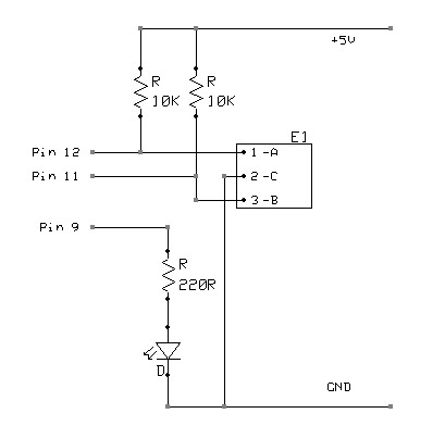
A rotary encoder generates two square wave outputs (A and B) that are 90 degrees out of phase. The number of pulses or steps produced per full rotation varies by model; for instance, the Sparkfun Rotary Encoder has 12...
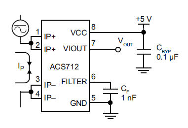
The primary component utilized is the ACS712 sensor from Allegro MicroSystems, designed for measuring current. It offers cost-effective and accurate solutions for AC or DC current sensing in industrial, commercial, and communication systems. A precise, low-offset, linear Hall sensor...
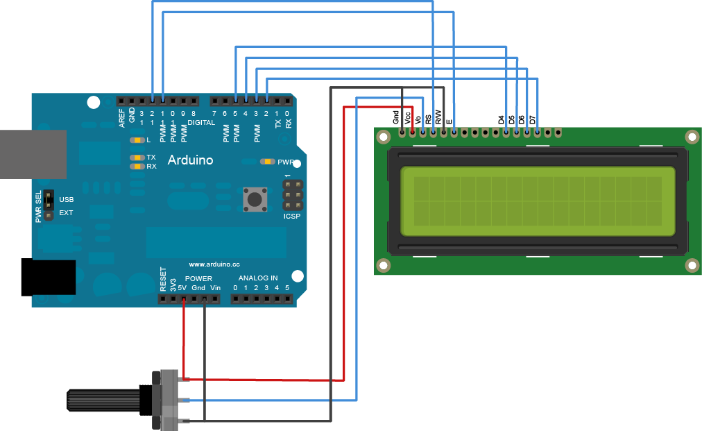
The Liquid Crystal Library enables control of LCD displays compatible with the Hitachi HD44780 driver. Many such displays are available, typically identifiable by their 16-pin interface. It is advisable to solder a pin header strip to the 14 (or...
On the Uno boards, there is an integrated circuit (IC) that functions as a USB to serial converter, enabling programming and communication with the Arduino from a computer. This IC is a surface-mounted device (SMD). The R3 version utilizes...

The circuit is a high-power car audio amplifier schematic. It functions as a car audio amplifier using the PA02 and LH0101 integrated circuits (ICs). Each IC delivers an output power of 30W with an 8-ohm impedance. The part list...
The initial step involves selecting software, and CadSoft Eagle was chosen due to the abundance of available tutorials, making it a suitable starting point. Once the process is understood, the choice of software can be reconsidered. For now, the...