
Electronic robot wiring schematic
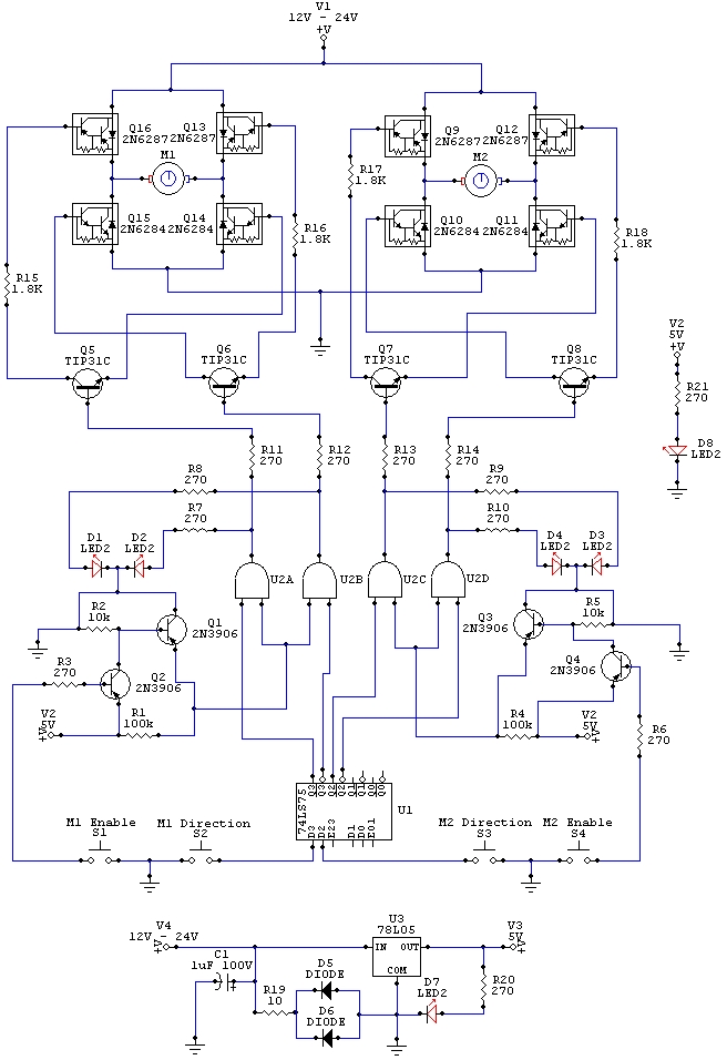
The wiring schematic serves as a crucial element in the design and operation of the robot, illustrating the interconnections between various components that facilitate movement. The diagram includes representations of the motors, microcontrollers, power supply, and the necessary connections that allow for the control signals to be transmitted effectively.
In this schematic, the motors are typically represented by their symbols, which indicate their type—such as DC motors or stepper motors—along with their rated voltage and current specifications. The microcontroller, which acts as the brain of the robot, is depicted with its pin configurations clearly labeled to show how it interfaces with the motors. Control signals from the microcontroller dictate the direction and speed of the motors, enabling precise movements.
Power supply connections are also illustrated, highlighting the voltage levels required for both the microcontroller and the motors. This ensures that all components receive the appropriate power without risk of damage. Additionally, any sensors that may be included in the design, such as distance sensors or gyroscopes, are marked on the schematic, showing how they connect to the microcontroller for feedback on the robot's position and orientation.
The use of Circuit Maker 2000 for designing this schematic allows for a clear and organized layout, making it easy for engineers to understand the relationships between components and troubleshoot any issues that may arise during the robot's operation. Proper labeling and color-coding of wires can further enhance readability, ensuring that the schematic serves as an effective reference throughout the development and testing phases of the robot.The wiring schematic played a big roll on the robot. This diagram is used to graphically display all the wiring of the motor controlling micro-components that gave the robot the ability to physically move forward, backward, left, right, and stop. (This diagram was designed in Circuit Maker 2000) 🔗 External reference
Related Circuits
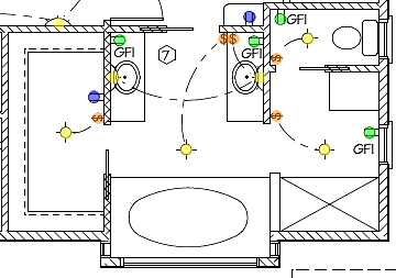
The following circuit illustrates the installation of a bathroom electrical wiring circuit diagram. Features include safety, energy savings, and enhancement of home functionality. This circuit diagram provides a comprehensive overview of the electrical wiring necessary for a bathroom installation. It...
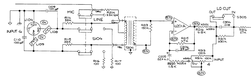
A student is working on a project related to active electronics as part of their second year in a bachelor's program in audio production. Active electronics refers to electronic circuits that require an external power source to operate, typically involving...

Metal detector schematic circuit using CS209A and a few electronic components. The metal detector circuit utilizing the CS209A integrated circuit is designed to detect metallic objects through the principle of electromagnetic induction. The CS209A is a specialized IC that facilitates...

In applications where a MOSFET is used to switch a load, it is relatively straightforward to incorporate short-circuit or overload protection. This can be achieved by utilizing the internal resistance RDS(ON), which generates a voltage drop proportional to the...
This document presents plans for a simple ground plane antenna that is effective in the FM band (88-108 MHz). It is constructed from a small plastic disk. The 6 x 6 loop antenna, designed by Graham Maynard, is highlighted...
Mechanical contacts have the disadvantage of wearing out. Therefore, it is practical to use an electronic touch switch in certain situations. This type of touch switch utilizes the resistance of human skin for its switching action. The schematic illustrates...
Warning: include(partials/cookie-banner.php): Failed to open stream: Permission denied in /var/www/html/nextgr/view-circuit.php on line 713
Warning: include(): Failed opening 'partials/cookie-banner.php' for inclusion (include_path='.:/usr/share/php') in /var/www/html/nextgr/view-circuit.php on line 713