
Electronic rodent control circuit
The electronic rodent control circuit operates by utilizing a combination of low and high voltage components to create a safe yet effective means of exterminating rodents. The isolated step-up transformer (B) is critical for elevating the voltage while ensuring safety from mains interference. The design ensures that the primary circuit remains isolated, preventing any accidental activation of the mains power, which could lead to hazardous situations.
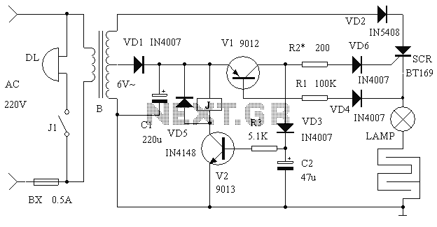
The circuit begins with the low voltage side, where the transformer generates approximately 6V. This voltage is rectified by diode VD1 and smoothed by capacitor C1, providing a stable DC voltage of about 7V for the control circuitry. The control mechanism is activated by the presence of a rodent. When a mouse crosses the grid, the presence is detected by the transistor V1, which switches the SCR into conduction mode, allowing high voltage to flow through the circuit momentarily. This high voltage is then applied to the lamp, which serves as a visual indicator while simultaneously delivering a lethal shock to the rodent.
The relay J is employed for alerting personnel, ensuring that the system is not only effective in exterminating rodents but also in maintaining operational awareness. The inclusion of an electric bell (DL) provides an auditory signal, prompting immediate action to remove the deceased rodents.
The careful selection of components, such as the specific types of resistors, capacitors, and semiconductors, is vital for the reliability and efficiency of the circuit. Each component plays a specific role, from voltage regulation to signal processing, ensuring the circuit operates as intended under various conditions. The overall design is a practical application of electronic principles to solve a common pest control problem, while also considering safety and functionality.It is said that the mice are more sensitive to electromagnetic fields, which is why the high-voltage grid rodent generally poor results. Electronic rodent control described here, no high-voltage power line usually, it does not cause mouse alert,
but as long as the body of a mouse trigger power grid, high-voltage power grid will immediately be able to instantly kill him, the rodent is better. working principle Circuit shown in Figure, B is an isolated step-up transformer. Due to the use of land as a grid electrode to prevent Warfarin mains security devices malfunction, the transformer circuit and mains isolation.
Secondary low pressure by about 6V VD1 rectifier, C1 filtering DC voltage of about 7V obtained for control. High voltage alternating current by a pulsating rectified voltage VD2 obtained power for tag. Way thyristor SCR for a high on / off control, SCR cathode connected to the power line by LAMP. Static, due to the base circuit of the transistor V1 suspension and off, SCR is also turned off the power grid to be only between a low DC voltage, thereby generating an electric field is weak, so that the mouse will not raise the alarm.
When a rat across the grid, V1 immediately turned the SCR triggered by high pressure pulsation LAMP immediately applied power line, the mice were killed. At the same time, V2 is saturated conduction, the relay J pull power, electric bell DL power and started to inform staff will promptly remove dead rats.
Component selection and production Component list is as follows Number Name Type Quantity R1 resistor 100K 1 R2 * 200 resistor to be adjusted 1 R3 resistance 5.1K 1 C1 electrolytic capacitors 220u 1 C2 electrolytic capacitors 47u 1 VD1,3,4,6 IN4007 4 VD2 rectifier diode rectifier diode IN5408 1 VD5 switching diode IN4148 1 V1 transistor 9012 1 V2 transistor 9013 1 SCR way SCR BT169 1 J relay 6V small 1 BX fuse 0.5A µ0.5cm 2cm 1 B transformer restructuring, 1 LAMP incandescent 60W / 220V 1 B selection control transformer 300W about restructuring, the low voltage winding removal, another with µ0.25mm enameled wire around 1200 turns, tapped at 13 turns for the low-voltage winding. J 6V with a small relay. The production of all components mounted on a circuit board. Available wire grid on the ground 2cm high number of porcelain insulation supporting wound channel is formed with a common circuit nails driven into the ground.
To enhance the effect, you can splash some water on the ground.
Related Circuits
The microphone preamplifier circuit design presented in this schematic utilizes the SSM2015 component manufactured by Precision Monolithics Inc. (PMI). This component provides high amplification with low noise characteristics (1.3nV/f). The design is configured to handle differential input signals and...
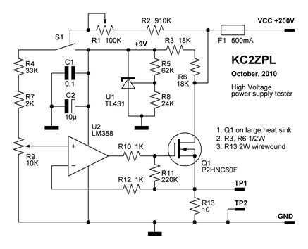
Now that these power supplies are available, it would be beneficial to evaluate their performance. Traditionally, an adjustable load (a robust resistor) is connected to the output to measure both output voltage and current at various points. This allows...

This circuit is a robust and efficient power amplifier suitable for various audio applications. It delivers 60W RMS output at a 50V supply with an 8 Ohm load. The design is user-friendly, allowing for the use of non-critical components...
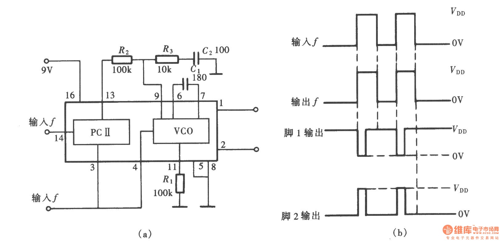
A frequency signal tracking circuit is implemented using a phase-locked loop (PLL) configuration, which is a fundamental application of the CD4046 integrated circuit. The circuit, illustrated in the accompanying chart, utilizes the CD4046 to form a PLL that effectively...
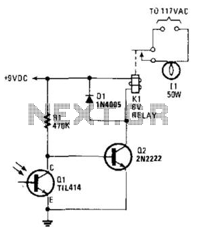
A phototransistor detects daylight. At dusk, it stops conducting, and Rl biases Q2, activating Kl, which turns on the light. At dawn, Ql begins to conduct, cutting off Q2. Kl deactivates, and the light turns off. The circuit utilizes a...
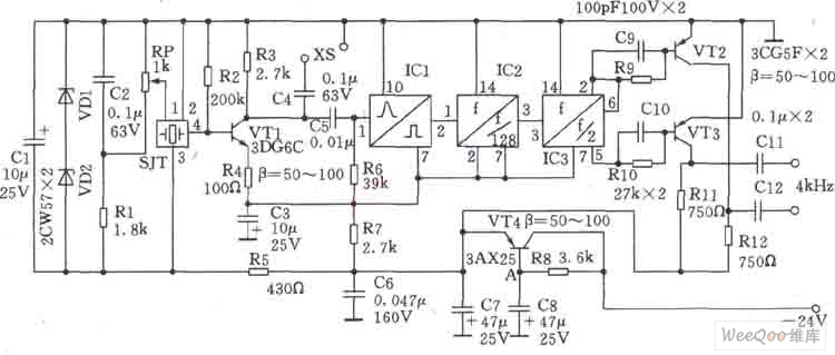
This circuit is a 1024 kHz temperature-compensated crystal oscillator. The circuit theory is illustrated. Due to the low output signal level of the circuit, a buffer using the following transistor VT1 is implemented for amplification. The base bias resistor...
Warning: include(partials/cookie-banner.php): Failed to open stream: Permission denied in /var/www/html/nextgr/view-circuit.php on line 713
Warning: include(): Failed opening 'partials/cookie-banner.php' for inclusion (include_path='.:/usr/share/php') in /var/www/html/nextgr/view-circuit.php on line 713