
KC2ZPLs Web Design and Electronic Home
The construction of this circuit emphasizes safety and usability, particularly when working with high voltages. The design allows for effective evaluation of power supply performance while minimizing risks associated with high voltage exposure. The use of commonly available components facilitates easy replication and modification for various applications in electronic testing and circuit evaluation.Now that I have these power supplies, wouldn`t it be nice to evaluate their performance Traditionally you connect an adjustable load (a "beefy" resistor) to the output and measure both the output voltage and the current in a number of spots. Then it`s easy to plot the ”U/ ”I relationship. Which is nothing more than output resistance at a given p oint. You could also connect an oscilloscope to the output and by varying the load, observe the amount of ripple, relative to both the amount of ripple before the stabilizer and the load value. The amount of ripple left over is especially important when working with sensitive receiving circuitry.
The additional difficulty posed by high voltage is that all the measurement gear has to be rated accordingly. My tube circuits require anywhere from 150V to 200V so it`s relatively easy to get a pair of multimeters.
However, using the oscilloscope is entirely a different matter. Most modern active probes can only be used with relatively low voltages. If you want to go higher, you have to extra purchase a special high-voltage kind which is expensive. I wanted to overcome these limitations by designing a load that is both easy to use and oscilloscope-safe. I didn`t want to go the large adjustable power resistor route and that meant an active high voltage load.
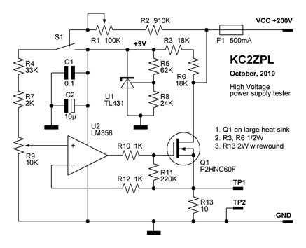
Accuracy wasn`t my primary concern. Often times you only need to see how this or that circuit approach compares to the ones before. The following is my attempt at designing the circuit using easy-to-obtain garden-variety components. The circuit here on the left is essentially an adjustable current sink. It`s powered by the DUT itself. A TL431 shunt regulator that forms the current setting 9V stable reference, also powers the Op-Amp. It "steals" about 4. 2 mA of current from the DUT. The LM358 ensures that the voltage in testpoint TP1 is exactly the same as on the slider of the current setting potentiometer R9. An external DC multimeter or an oscilloscope is connected to the testpoints TP1 and TP2 to measure the voltage drop across R13.
The maximum current of 200mA through the R13 translates to maximum of 2V on multimeter`s scale. In other words the indication is divided by 10 and thought of as current in milliamps. This way no matter which instrument I use, they don`t see the full dangerous output. What`s the switch S1 for, you ask When the switch is in the position shown in the picture, the whole device behaves as one giant resistor. The current through it is then proportional to the voltage across it plus the aforementioned 4. 2 mA. When the switch is in the lower position, the current through the circuit is dependent on R9 setting only.
My prototype was built Manhattan-style on a piece of single-side PCB. It holds all the components with the exception of the set pot R9, mode switch S1 and terminal poles TP1, TP2. All of these are mounted on the front panel and wired to the PCB. Resistors R3 and R4 have to be able to dissipate at least 1/2W each. The current measuring resistor R13 needs to have a higher rating of at least 2W. I found mine on a junked PC power supply board. Be aware that when in operation, the MOSFET needs to dissipate 0. 2A x 200V = 40W. I used an old Pentium-II style CPU heatsink to cool it. Definitely use a good quality heatsink compound to maximize the heat transfer between the body of the MOSFET and metal.
I profusely apologize but that`s the only photo I have of my device. It`s a bit fuzzy but hopefully the general idea of how I constructed mine should be clear from it. It was taken while it was still under development. Shortly after being put in the box it was loaned out to a friend of mine who restores old radios. Once I get it back, I promise I will upload more pictures. 🔗 External reference
Related Circuits
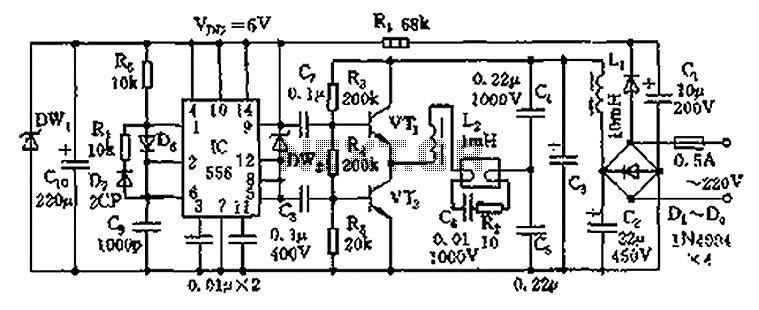
The circuit operates as an electronic ballast for fluorescent lamps, incorporating a rectifier filter circuit, a high-frequency oscillation circuit, and an output circuit. The rectifier filter circuit consists of a rectifier diode (VD1) and filter capacitors (C1, C2). The...
The water resource is being transformed into a valuable and rare commodity. Consequently, promoting water-saving irrigation has become a priority for countries worldwide to address the water resource crisis and achieve agricultural modernization. This text proposes a cipher scheme...

The sound produced imitates the rise and fall of an American police siren. When first switched on, the 10 µF capacitor is discharged, and both transistors are off. When the push button switch is pressed, the 10 µF capacitor...
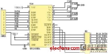
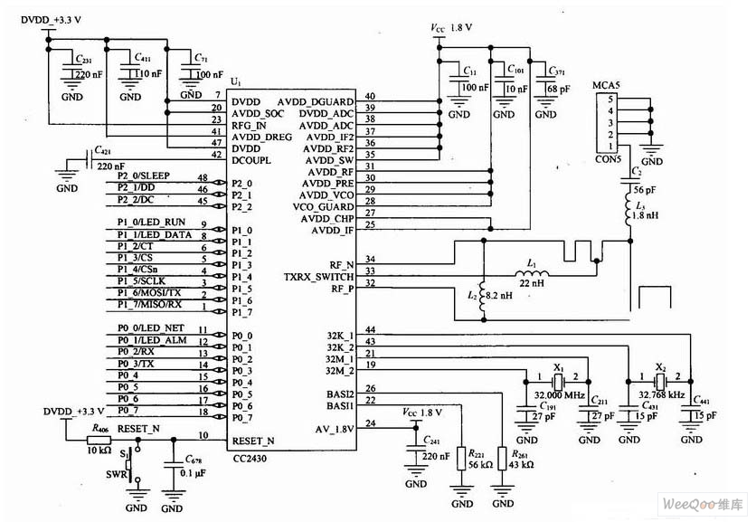
The intellectual wireless signal transducer is designed for major transducer applications and typical sensor output signal designs. It is essential to first analyze the outgoing signals from the transducer. Typically, the output of the transducer is a standard electric...

Metronome is an electronic device that keeps rhythm by making regulated clicking sounds, device used to keep the beat while playing a musical instrument. The circuit is an old design to build, but you will find it useful. The metronome...
A fast electronic fuse designed to operate on 230V AC with an adjustable trip current. When the current through the load exceeds a level determined by the user, the fuse will trip to protect the circuit. The electronic fuse functions...
Warning: include(partials/cookie-banner.php): Failed to open stream: Permission denied in /var/www/html/nextgr/view-circuit.php on line 713
Warning: include(): Failed opening 'partials/cookie-banner.php' for inclusion (include_path='.:/usr/share/php') in /var/www/html/nextgr/view-circuit.php on line 713