
Electronic Siren
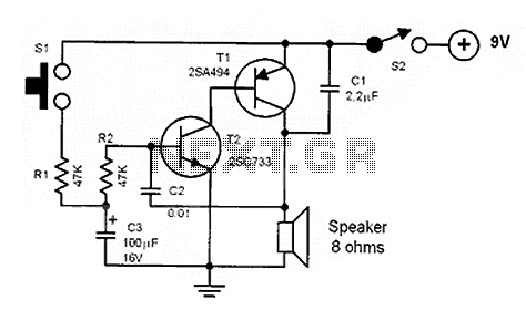
The circuit described functions as an audio oscillator, emulating the characteristic sound of a police siren through a series of transistors and capacitors. The BC108B and 2N3702 transistors serve as the primary switching elements, with the BC108B acting as the main control transistor and the 2N3702 as a secondary amplifier that responds to changes in the collector voltage of the BC108B.
When the push button switch is engaged, the 10µF capacitor begins to charge, leading to a gradual increase in voltage at the base of the BC108B. This slow turn-on characteristic creates a ramp-up effect in the sound output, simulating the rising pitch of a siren. Once the button is released, the discharge path for the 10µF capacitor through the resistors allows for a gradual decrease in voltage, resulting in a falling pitch of the sound.
The 22nF capacitor plays a crucial role in the rapid switching of the 2N3702 transistor. Its quick charge and discharge characteristics facilitate a feedback loop that enhances the oscillation frequency of the circuit. The interaction between the charging and discharging of the capacitors and the switching of the transistors creates a modulated sound wave that mimics the siren's rise and fall.
The choice of resistors, specifically the 22kΩ and 100kΩ, along with the capacitors, determines the timing characteristics of the oscillation. Adjusting these values can lead to variations in the frequency and tone of the siren sound. The inclusion of different speaker impedances, such as a 64Ω loudspeaker, allows for flexibility in sound output and volume levels.
Overall, this circuit exemplifies a simple yet effective method for generating audio signals that can be tailored for various applications, including alarms and sound effects in electronic projects.The sound produced imitates the rise and fall of an American police siren. When first switched on the 10u capacitors is discharged and both transistors are off. When the push button switch is pressed to 10u capacitor will charge via the 22k resistor. This voltage is applied to the base of the BC108B which will turn on slowly. When the switch is re leased the capacitor will discharge via the 100k and 47k base resistors and the transistor will slowly turn off. The change in voltage alters the frequency of the siren. The oscillator action is more difficult to work out. As the BC108B transistor switches on its collector voltage falls and so the 2N3702 transistor is switched on.
This happens very quickly ( less than 1us). The 22n capacitor will charge very quickly as well. As this capacitor is connected between the collector of the 2N3702 and the base of the BC108B, it soon reaches almost full supply voltage. The charging current for the capacitor is then much reduced and the collector emitter voltage of the 2N3072 is therefore increased; the collector potential will fall.
This change in voltage is passed through the 22n capacitor to the base of the BC108B causing it to come out of saturation slightly. As this happens its collector voltage will rise and turn off the 2N3072 transistor more. This continues until both transistors are off. The 22n capacitor will then discharge via the 100k, 22k resistor, the closed push button switch, 9V battery, the speaker and 56 ohm resistor.
The discharge time takes around 5-6msec. As soon as the 22n capacitor is discharged, the BC108B transistor will switch on again and the cycle repeats. The difference in voltage at the collector of the BC108B (caused by the charging 10u capacitor) causes the tone of the siren to change.
As the 10u capacitor is charged, the tone of the siren will rise, and as it is discharged, it will fall. A 64 ohm loudspeaker may be used in place of the 8 ohm and 56 resistor, and the values of components may be altered to produce different sound effects.
🔗 External reference
Related Circuits
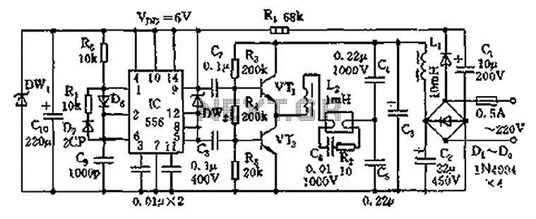
The circuit operates as an electronic ballast for fluorescent lamps, incorporating a rectifier filter circuit, a high-frequency oscillation circuit, and an output circuit. The rectifier filter circuit consists of a rectifier diode (VD1) and filter capacitors (C1, C2). The...
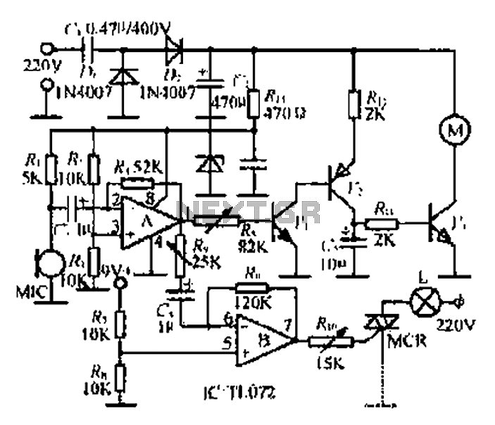
A microphone (MIC) is used to capture sound, which is then converted into a voltage signal. An operational amplifier (op-amp A) acts as a buffer; one output is directed to a motor drive circuit to control the motor's rotation...
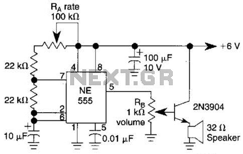
Ra sets the rate while RH sets the volume of clocks in the speaker. The 555 is configured as a low frequency oscillator. The circuit is powered by a 6 V battery. The circuit utilizes a 555 timer IC configured...
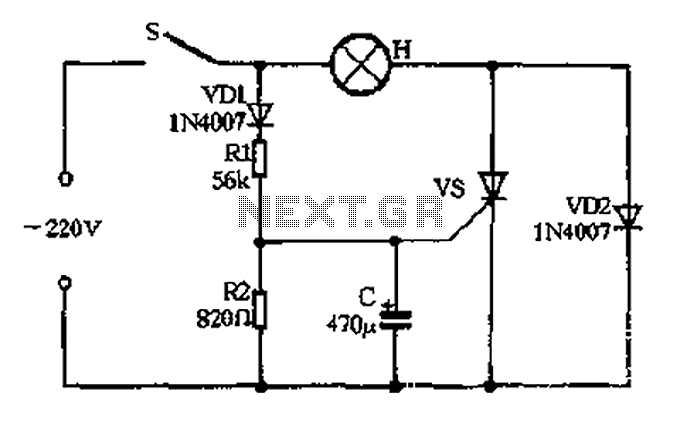
The circuit operates as follows: When the momentary switch S is activated, the voltage across the capacitor cannot change instantly, resulting in zero voltage across the SCR, which does not trigger. Consequently, the voltage cut-off occurs. In this scenario,...
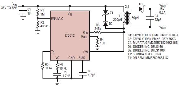
A straightforward dual 15-volt power supply electronic circuit can be created using the LT3512 switching regulator IC produced by Linear Technology. This basic 15-volt DC power supply operates with an input voltage range of 36 to 72 volts and...
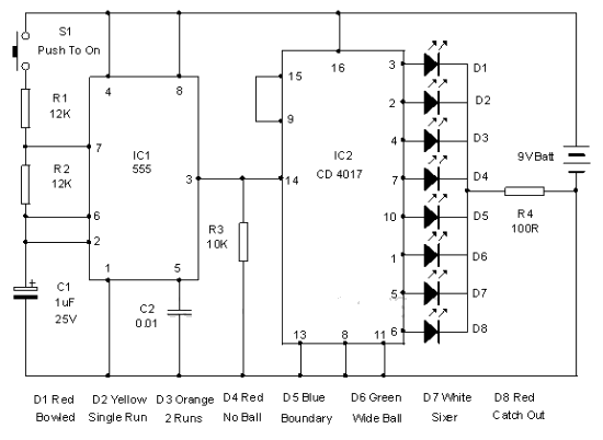
This electronic cricket device is a gift for children. This simple battery-powered circuit can be used to simulate a cricket match with friends. Each LED in the circuit represents various statuses of the cricket match, such as a six,...