
Electronic Ballast circuit diagram
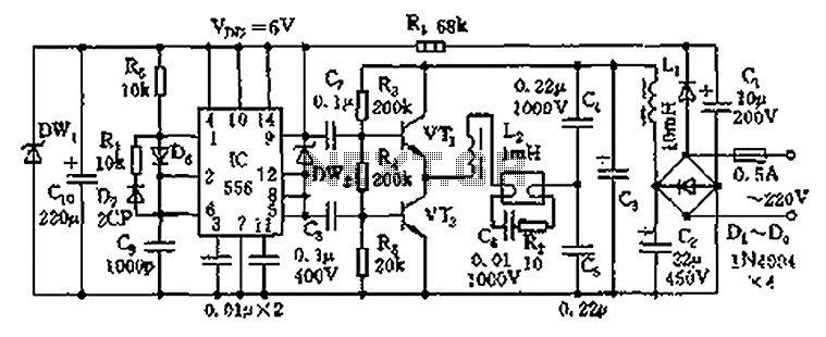
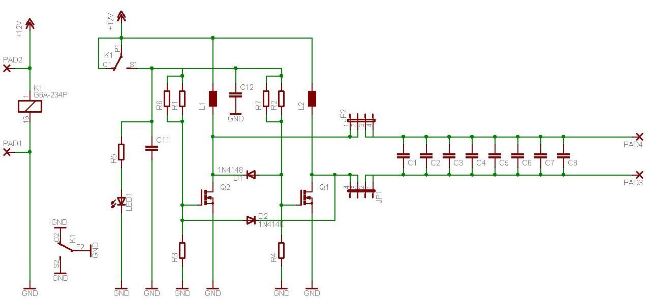
The electronic ballast circuit for fluorescent lamps is designed to efficiently convert mains AC voltage into a high-frequency output suitable for lamp operation. The rectifier filter circuit's primary role is to convert the incoming 220V AC into a stable DC voltage, typically around 280V, which is necessary for the subsequent stages of the ballast. This conversion is achieved using a diode (VD1) that allows current to flow in one direction, while capacitors (C1 and C2) smooth out the rectified signal, minimizing voltage ripple and ensuring a steady DC supply for the oscillator.
The high-frequency oscillation circuit is crucial for driving the fluorescent lamps. It comprises two transistors (V1 and V2) that operate in a push-pull configuration, rapidly switching on and off to generate high-frequency alternating current. The oscillation frequency is determined by the values of the resistors (R1, R7) and capacitors (C3, C4, C6), which form a feedback loop that stabilizes the oscillation. The transformer (T) is integral to this process, as it steps up the voltage and provides isolation while facilitating energy transfer between the primary and secondary windings (W1 and W3).
The output circuit consists of inductors (L1 and L2) and capacitors (C7 to C10), which work together to filter and shape the output waveform delivered to the fluorescent tubes. The inductors help to limit the current and provide a smooth, continuous flow of energy to the lamps, while the capacitors ensure that the voltage remains stable during operation. When the fluorescent tubes (ELI and EL2) are powered, their filaments heat up, reducing their resistance and allowing them to draw the necessary current to maintain illumination.
This electronic ballast circuit is characterized by its efficiency and ability to provide a reliable light source while minimizing energy consumption and heat generation. By operating at high frequencies, the circuit reduces flicker and enhances the performance of the fluorescent lamps, ensuring a longer lifespan and better light quality. Circuit works The fluorescent lamp electronic ballast circuit by the rectifier filter circuit, high-frequency oscillation circuit and output circuit. Circuit, the rectifier fil ter circuit consists of a rectifier diode VDV D4 and filter capacitor C1, C2 composition; high-frequency oscillator by the transistor vi, V2, a resistor R1 R7, capacitor C3, C4, C6, diode VD5 and a V D8 high frequency transformer T (W1 W3 a wound on the same ring, the formation of a high-frequency transformer) composition; from the output circuit choke L1, L2 and capacitor CL-C10 components. When energized, the AC 220V voltage by a V D4 rectifier VD1 and Cl, C2 filtering, in A, C generated across the DC voltage of about 280V, and high-frequency oscillator power supply.
Transistor V1, V2 in the capacitor C3, C4, C6 and C10 under a winding W3 W1 a role T, and soon turned into a high-frequency alternating oscillation state off, resulting in an approximately sinusoidal between A, B two points high-frequency alternating voltage waveform, voltage through L1, the LZ and a C7 to C10 plus fluorescent tubes ELI and EL2 filament, making ELI and EL2 starter lit. After ELI and EL2 is lit, its filament resistance sharp decline, C9 and C10 high ignition voltage drop across the normal value, maintain normal light fluorescent tubes.
Related Circuits
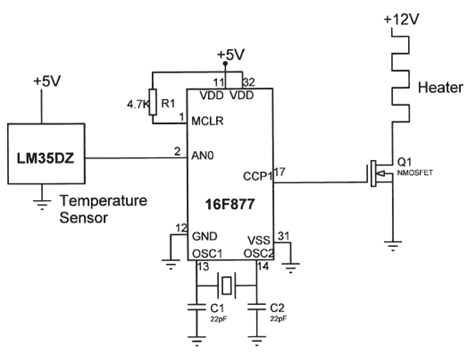
The electrical circuit diagram of this temperature control circuit consists of a 3-pin analog temperature sensor (LM35DZ), a built-in A/D converter microcontroller (PIC16F877), and the heater driver (IRL1004). The temperature control circuit utilizes the LM35DZ, a precision analog temperature sensor...
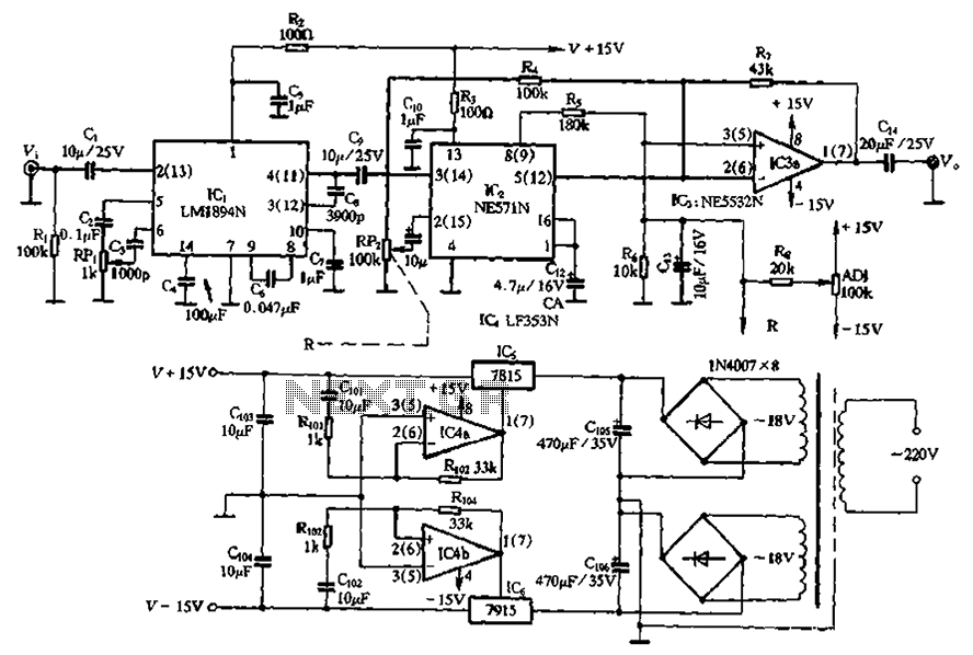
The NE571 and LM1894N form a dynamic expander circuit that enhances performance. This dynamic expander utilizes a variable bandpass filter with the LM1894N. It is particularly effective for dynamic expansion, requiring an RMS rectifier to mitigate noise modulation effects,...
This infrared light valve has more parts, so it works better and more reliable for alarms. The circuit responds less ambient light. The light valve consists of a transmitter and a receiver. The transmitter consists of a NE 555...
Instructions to assemble a small project on wireless energy transfer. If anyone has a simple schematic suitable for beginners, please share or provide instructions. The simplest one found so far is from a Hungarian YouTube channel, but it is...
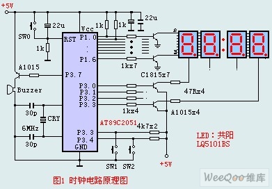
The circuit design incorporates an anodic Nixie tube for the LED display. It utilizes the LQ5101BS general luminous diode, with the driving transistor being either the 2SA1015 or 2SC1815 types, which are readily available. Additionally, low-power transistors such as...
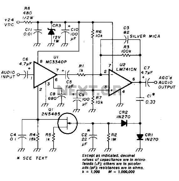
An audio signal applied to the input VI is passed through the operational amplifier 741, designated as U2. After amplification, the output signal V2 is sampled and sent to a negative voltage doubler/rectifier circuit composed of diodes CR1 and...
Warning: include(partials/cookie-banner.php): Failed to open stream: Permission denied in /var/www/html/nextgr/view-circuit.php on line 713
Warning: include(): Failed opening 'partials/cookie-banner.php' for inclusion (include_path='.:/usr/share/php') in /var/www/html/nextgr/view-circuit.php on line 713