
Electronic toss circuit
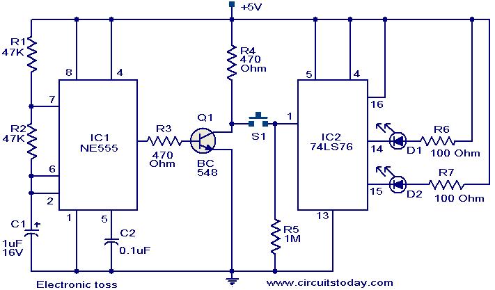
The circuit operates by generating a continuous square wave signal from the NE555 timer, which serves as the clock input for the JK flip-flop. The NE555 timer is configured in an astable mode, producing a pulse every 100 milliseconds, resulting in a toggling frequency of 10 Hz. This frequency is suitable for visual indication through LEDs, making it easy for users to perceive the outcome of the toss.
The transistor Q1 plays a crucial role in inverting the output signal from the NE555 timer. It ensures that the toggling action is appropriately transferred to the JK flip-flop. When the push-button switch S1 is activated, it allows the clock pulses from the NE555 timer to reach the JK flip-flop, which is configured to toggle its outputs on each clock pulse.
The 74LS76 dual JK flip-flop is set up such that its outputs (pins 14 and 15) represent the two possible outcomes of the toss. When the button is pressed, the outputs change states, causing the connected LEDs to light up. The persistence of vision effect creates the illusion that both LEDs are glowing at the same time. Once the button is released, the flip-flop maintains the last state, with one LED remaining lit, indicating the result of the toss.
This circuit can be further enhanced by incorporating features such as sound output or additional visual indicators to improve user interaction. The basic design, however, effectively demonstrates the principles of digital electronics and provides a simple yet functional solution for simulating a coin toss.The circuit given here can be used for tossing head or tail. There are many games in which a tossing is required to start and this circuit can be used in all such instances. The circuit uses two ICs NE 555 timer (IC1) and 74LS76 dual JK flip flop (IC2). The IC 1 is wired as an astable multi vibrator operating at 10Hz. The output of IC1 is inverted b y using the transistor Q1. The collector of Q1 is connected to the pin 1 of IC2 via the push button switch S1. The IC2 is wired in toggle mode. When push button S1 is pressed the output pins 14 and 15 of IC2 starts toggling in state. The LEDs connected to these pins also toggles (Since the frequency of toggling is 10Hz, we feel both LEDs glowing). When push button S1 is released either one of the LED remains ON indicating the head or tail. 🔗 External reference
Related Circuits

The circuit consists of a delay loop, discriminators, output circuits, power supply, and indicator lights, divided into five parts. The power regulation is achieved through a resistor (R), while the power regulator is constructed using a voltage source. In...
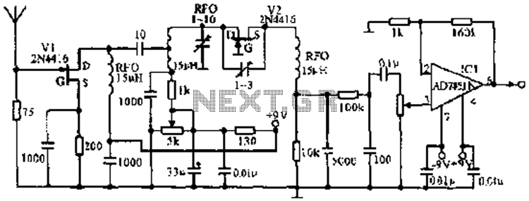
The image illustrates the JFET VHF band super-regenerative receiver circuit. It features high discharge tubes V1 and V2, which serve as the super-regenerative detector tubes. IC1 functions as a low-frequency amplifier. The circuit exhibits a sensitivity of better than...
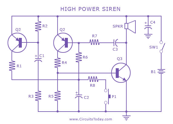
A siren circuit diagram that generates a strong, high-power siren or alarm sound using complementary transistor pairs BC 557 and BC 337, arranged as an oscillator. The described siren circuit employs a pair of complementary transistors, BC 557 (a PNP...
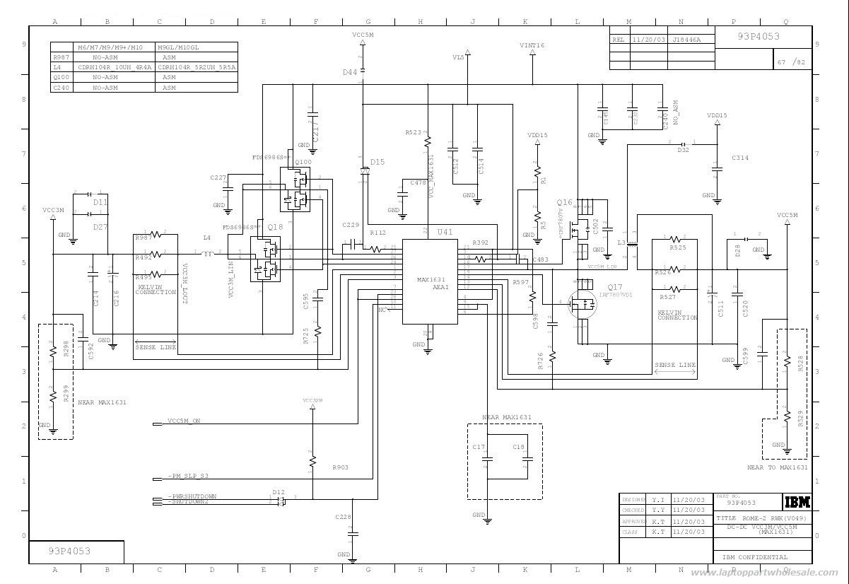
This is an IBM ThinkPad T40 power control circuit. This circuit is based on the MAX1631 IC, which is a multi-output, low-noise power supply. The IBM ThinkPad T40 power control circuit utilizes the MAX1631 integrated circuit (IC) to provide stable...
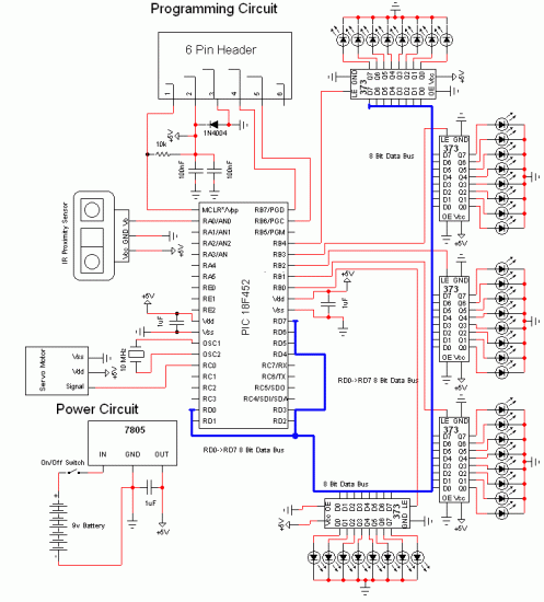
Chris from PyroElectro.com has an informative article detailing a do-it-yourself radar system constructed using the PIC18F452 microcontroller. This project is an excellent hobbyist endeavor, although the schematic design is quite complex. The system integrates three primary components to form...
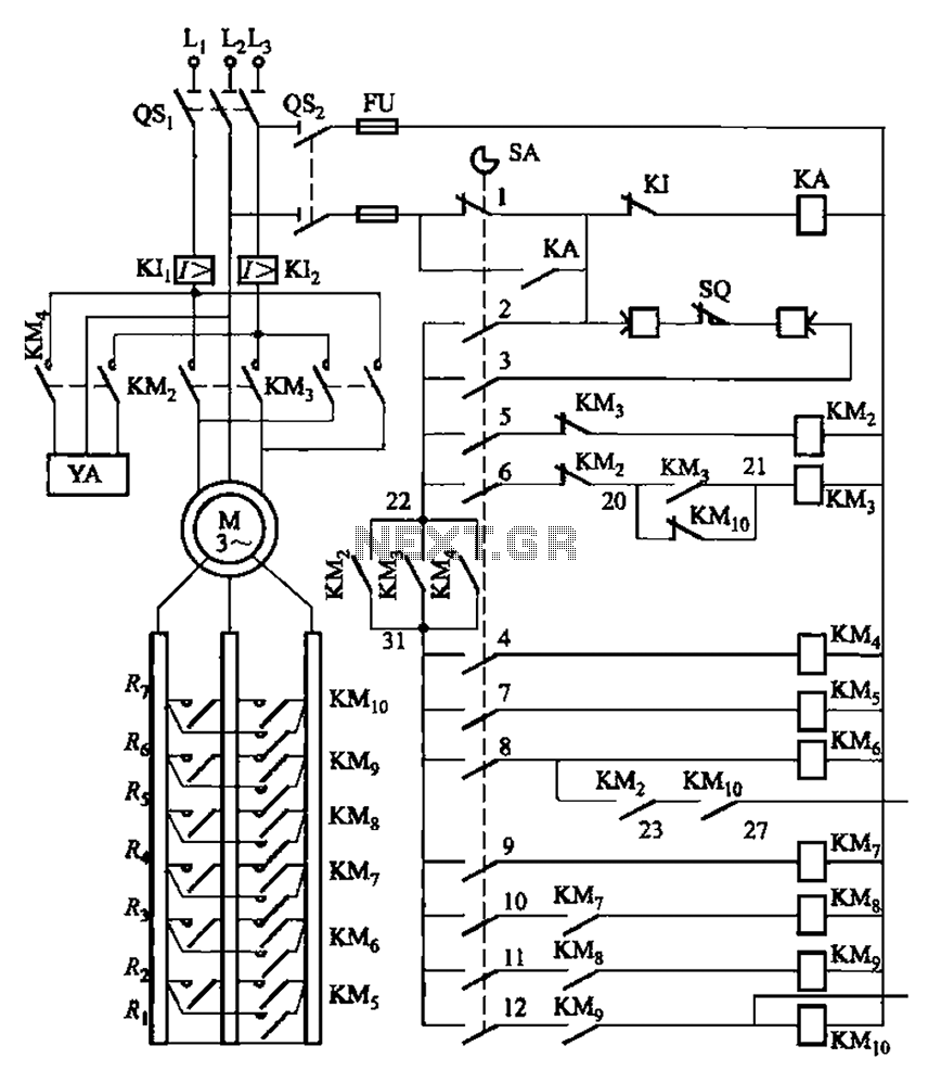
The system is managed by the master controller LKl-12/90 and a magnetic disk control unit PQR10A, which includes a control circuit. The cam control device SA is responsible for contact closure, as indicated in Table 8-5. The main electrical...