
IBM ThinkPad T40 Power Control Circuit With MAX1631 IC
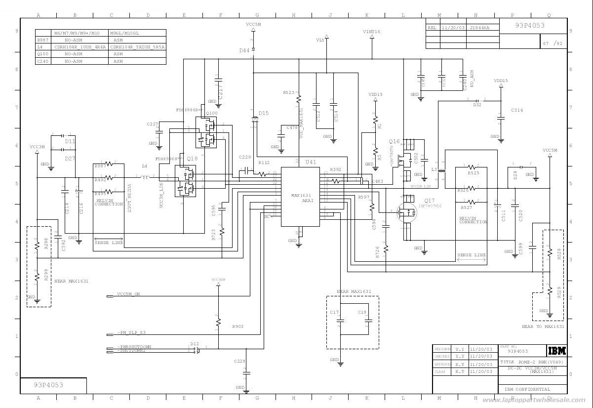
The IBM ThinkPad T40 power control circuit utilizes the MAX1631 integrated circuit (IC) to provide stable and efficient power management for the laptop. The MAX1631 is designed to deliver multiple output voltages, which are essential for powering various components within the laptop, such as the CPU, memory, and peripheral devices.
The circuit typically includes several key components: the MAX1631 IC itself, input and output capacitors, resistors for voltage setting, and possibly inductors for filtering purposes. The IC operates by receiving a single input voltage, which it regulates down to the required output levels. It features low quiescent current, making it suitable for battery-operated devices where power efficiency is critical.
In this application, the MAX1631 can be configured to provide multiple output voltages, which may include 5V, 3.3V, and 1.8V, depending on the specific needs of the components being powered. The outputs are typically designed with low dropout characteristics, ensuring that the voltages remain stable even under varying load conditions.
To implement this circuit, careful attention must be paid to the layout to minimize noise and ensure proper thermal management. The use of bypass capacitors close to the IC pins is crucial for filtering high-frequency noise, while larger output capacitors can help maintain voltage stability during transient loads.
Overall, the MAX1631-based power control circuit in the IBM ThinkPad T40 is a critical component that ensures reliable operation and performance of the laptop by providing the necessary power with low noise and high efficiency.This is a IBM ThinkPad T40 Power control circuit. This circuit based on the MAX1631 IC. MAX1631 IC is a Multi-Output, Low-Noise Power-Supply .. 🔗 External reference
Related Circuits
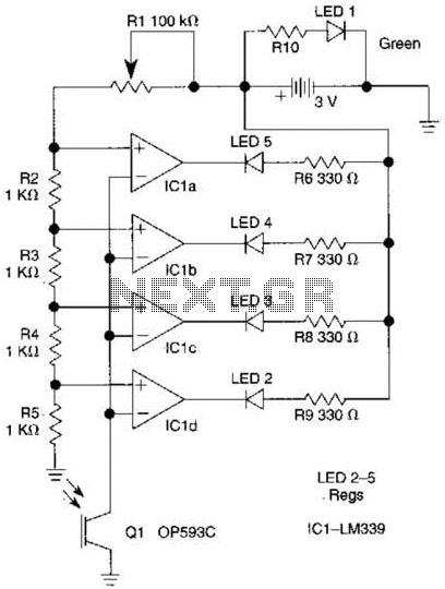
The outputs from the comparators will transition, in sequence, from high to low as the input voltage exceeds the reference voltage applied to each comparator. The output LEDs will activate sequentially as the voltage increases. The inverting inputs of...
The tuner is programmable via I²C-Bus and provides a FBAS signal at its output. There is also the homepage of Georg Acher containing information about this tuner. A control circuit has been developed for this tuner using the AT89C2051...
The amplifier is based on the commonly used class-AB complementary power amplifier with compound pair output transistors. The system uses a TL074 quad opamp to drive the output transistors. As can be seen from figure 1, A2 is used to...
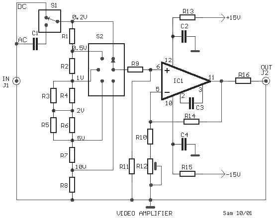
This is a schematic diagram of a video amplifier circuit, built using the very high-speed operational amplifier IC LH0032. Parts List: R1 = 15KΩ, R2, R3, R4 = 10KΩ, R5, R6, R7, R8, R9 = 1KΩ, R10 = 820Ω,...
The widespread application of Flash technology in microprocessors has led to significant advancements in the development and utilization of one-chip computers. Designers have transitioned from traditional in-circuit emulators (ICE) and JTAG interfaces to more cost-effective and user-friendly development methods....
This simple charger utilizes a single transistor as a constant current source. The voltage across the pair of 1N4148 diodes biases the base of the BD140 medium power transistor. The circuit operates by employing the BD140 transistor to regulate the charging...
Warning: include(partials/cookie-banner.php): Failed to open stream: Permission denied in /var/www/html/nextgr/view-circuit.php on line 713
Warning: include(): Failed opening 'partials/cookie-banner.php' for inclusion (include_path='.:/usr/share/php') in /var/www/html/nextgr/view-circuit.php on line 713