
PQR10A type magnetic disk control panning control circuit
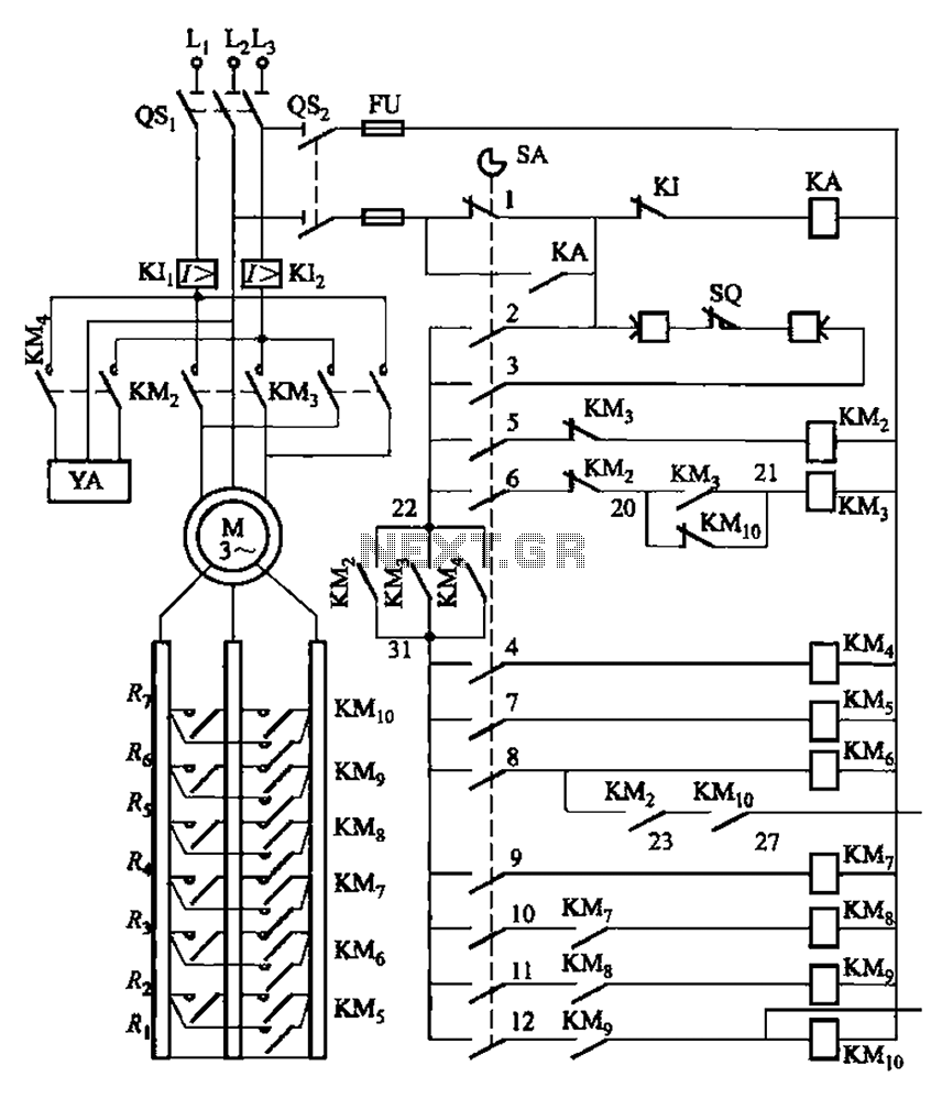
The described system operates as a sophisticated control mechanism for motor management, utilizing a combination of relays, contactors, and control circuits to ensure safe and efficient operation. The master controller LKl-12/90 serves as the central processing unit, coordinating the actions of various components based on input signals and operational requirements.
The magnetic disk control unit PQR10A plays a crucial role in the control circuit, managing the execution of commands issued by the master controller. The cam control device SA facilitates the physical connection and disconnection of circuits, allowing for precise control over motor operations.
Key components such as the osi power switch and os2 control circuit switch are essential for initiating and regulating power flow to the system. The control reversing contactors KM3 and KM2 are designed to reverse the direction of the motor, with built-in interlocks that prevent accidental operation, enhancing safety during use.
The KA zero pressure relay is critical for ensuring that the motor does not start under unsafe conditions, providing voltage protection and preventing operation when pressure levels are not adequate. The overcurrent relays KI- and KI2 serve to protect the motor from damage due to excessive current, effectively safeguarding against overload and short circuits.
Limit switches integrated into the lifting mechanism provide feedback on the position of the motor, ensuring that operations are halted when maximum or minimum positions are reached. The YA brake contactor is responsible for engaging mechanical brakes, facilitating safe stopping of the motor during operation.
The reverse contactors KM5 and KMs, along with the acceleration contacts KM7 to KM1, enable precise control over motor speed and direction, allowing for smooth transitions between operational states. The master controller SA is integral to managing these functions, issuing commands based on the desired operational mode, whether it be lifting, lowering, or braking.
Overall, the system is designed to operate efficiently across multiple gears, with 13 distinct locations available for operation. The configuration of 12 pairs of contacts allows for flexibility in operational modes, ensuring that the system can adapt to various requirements as outlined in the referenced table. This comprehensive control architecture ensures that the motor operates safely and effectively under a range of conditions. By master controller LKl-12/90 and a magnetic disk control PQR10A composed of a control circuit. Cam control device SA contact closure is shown in Table 8-5. The main electrica l effect: osi power switch; os2 control circuit switch; KM3, KMz control reversing contactors, with mechanical and electrical interlocks between them. KA zero pressure relay, motor starting voltage protection and zero protection effect; KI-, KI2 overcurrent relay, the motor from overload, short circuit protection; so as to rise from the lifting mechanism limit switches.
YA brake contactor, starting the motor mechanical braking action. Reverse contactor KM5, KMs and accelerate contacts KM7 ~ KM1., Or access to short circuit in the electric rotor powerful horse, of the motor speed. Master controller SA to issue instructions, the motor for a variety of operating or braking. It handles 13 Location: on the rise, decline of 6 gear, there is a zero gear. Its 12 pairs of contacts on different gear closed case from the table marked out.
Related Circuits
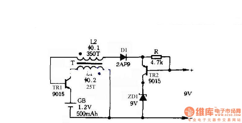
The circuit does not require a separate power switch or transformation to control the switches on the table. It offers advantages such as low power consumption, stability, reliability, and no impact on instrument accuracy. The transformer T in the...
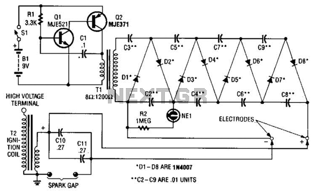
This circuit employs a transistor oscillator and a voltage multiplier to charge capacitors CIO and CI1 to a high voltage. When the spark gap breaks down, T2 generates a high-voltage pulse through the discharge of capacitors CIO and CI1...
The microcontroller IC is a device that resembles a typical integrated circuit. However, it contains a miniature computer within its architecture. This device can serve as a replacement for transistors. Microcontroller integrated circuits (ICs) are compact, multifunctional devices that integrate...
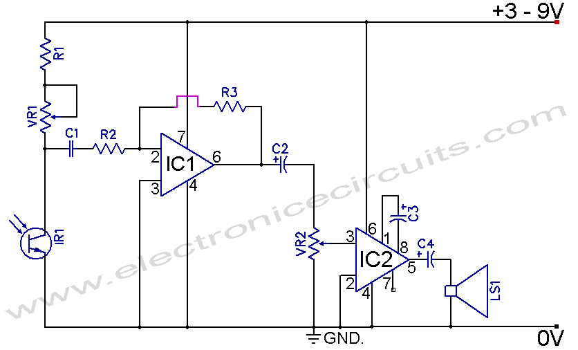
Infrared Remote Control Tester Circuit. This is a simple circuit that can be built to test infrared remote controls. The circuit utilizes an... This infrared remote control tester circuit is designed to verify the functionality of infrared remote controls commonly...
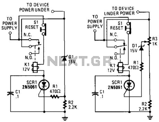
If circuits experience frequency overvoltage conditions, continually replacing blown fuses can become quite costly. This shutdown circuit addresses that issue by substituting the fuse with a relay and a low-current SCR. When the input voltage exceeds the threshold established...
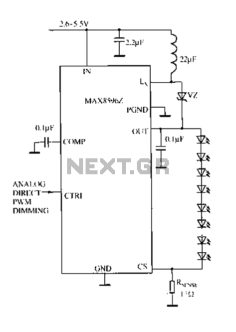
Driving a series of white LEDs allows for a consistent current to flow through each LED, resulting in uniform brightness. However, a disadvantage of this series configuration is that the driving voltage must account for the forward voltage drop...
Warning: include(partials/cookie-banner.php): Failed to open stream: Permission denied in /var/www/html/nextgr/view-circuit.php on line 713
Warning: include(): Failed opening 'partials/cookie-banner.php' for inclusion (include_path='.:/usr/share/php') in /var/www/html/nextgr/view-circuit.php on line 713