
electronic touch switch
The circuit design employs the LM393 dual comparator, which is adept at comparing two voltage levels and generating an output based on the comparison. The non-inverting input of IC1a is connected to a power supply through resistor R1, ensuring that it receives a steady voltage in the idle state. The inverting input is calibrated using resistors R2 and a series of diodes (D3 to D5) to create a reference voltage that is slightly lower than the non-inverting input, facilitating the desired switching behavior.
The configuration of the touch switch, with its conductive contacts positioned on a non-conductive substrate, allows for the detection of a change in resistance when touched by a finger. The skin's moisture plays a crucial role in determining the resistance, which can vary significantly. The circuit's sensitivity to this resistance change enables it to respond to even minor capacitance introduced by a human body.
The output of IC1a is fed into IC1b, which serves to invert the signal. The voltage divider formed by resistors R4 and R5 ensures that the non-inverting input of IC1b is set to a level that is lower than the inverting input under normal conditions, keeping the output low. When the touch contacts are activated, the change in voltage at the non-inverting input of IC1b prompts it to toggle the output state.
The design also incorporates a capacitor (C1) in conjunction with resistor R3 to filter out the 50 Hz noise from the mains. This filtering is essential to prevent false triggering of the output, allowing for a clean pulse signal that can be utilized in downstream applications.
Overall, this circuit provides a simple yet effective method for creating a touch-sensitive switch, suitable for various low-power applications where isolation and safety are paramount. However, careful consideration should be given to its use in critical systems due to its susceptibility to interference and unintended activation.The schematic shows the design of a circuit that senses the resistance of the skin and converts it into a useful switching signal. The touch switch contacts can be made from two small metal plates, rivets, nails, etcetera, which are placed close together on a non-conducting surface.
In this circuit a comparator of the type LM393 has been used. In the idle state there is, via R1, a voltage equal to the power supply voltage on the non-inverting input of IC1a. Because the inverting input of IC1a is set with R2 and D3 to D5 at the supply voltage minus 1. 8 V, the open-collector output of IC1. a is, via R3, equal to the power supply voltage. This voltage is inverted by IC1. b. The voltage at the non-inverting input of IC1. b amounts to half the power supply voltage (through voltage divider R4 and R5) and is lower than the voltage on the inverting input. The output of IC1. b is therefore a 0`. If the two touch contacts are bridged with a finger, the voltage at the non-inverting input will become low enough to cause the comparator to toggle state.
The moistness of the skin results in a resistance of 1 to 10 MR. If this circuit is used in the vicinity of equipment that`s connected to the mains, then it can be sufficient to touch only the upper contact to operate the switch, provided that the circuit has been earthed. The body then acts as an antenna which receives the 50 Hz (or 60 Hz) from the mains. This is enough to toggle IC1. a at the same 50 Hz. C1/R3 prevent this 50 Hz from reaching the input of IC1b and provide a useable pulse` of about 10 s at the output of IC1.
b. Note that a fly walking across the touch switch conducts enough to generate a switching signal. So do not operate important things with this circuit (such as the heating system or the garage door). Do not make the wires between the touch contacts and the circuit too long to prevent picking up interference.
The power supply voltage for the circuit is not very critical. Any regulated DC voltage in the range from 6 to 20 V can be used. 🔗 External reference
Related Circuits

A radio-controlled electronic flash is an essential tool in any photographer's kit. Professionals frequently utilize them, such as wedding photographers. A radio-controlled electronic flash system typically consists of a transmitter and one or more receivers. The transmitter, often mounted on the...
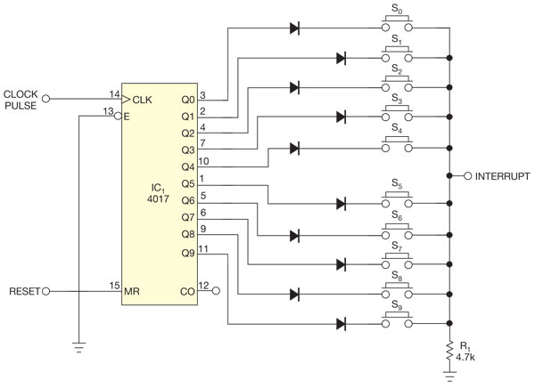
There are several methods to read multiple switch inputs using a reduced number of microcontroller unit (MCU) pins. One approach involves using an analog MCU pin to read multiple switches by assigning a unique voltage to each switch through...

When the ON/OFF button is pressed once, the equipment goes on and stays on. It goes off when the button is pressed again. The circuit is straightforward. It uses a JK CMOS Flip-Flop with its JK terminals tied high...
Described here is a very inexpensive solution to many phono-controlled applications like remote switching on, for instance, or activating a camera, tape recorder, burglar alarms, toys, etc. The circuit given here employs a condenser microphone as the pick-up. A...

The BA2181 is a dimming controller that utilizes ASIC technology for touch-based stepping dimming of lights. It operates with low power consumption and has strong anti-interference capabilities. The device is compact and stable, making it suitable for various applications....
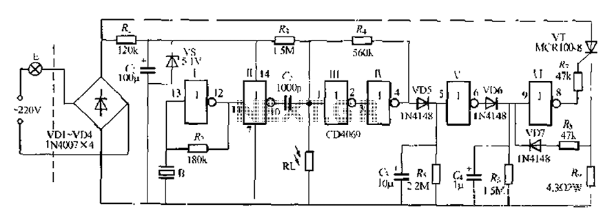
The circuit is designed for sound and light control of stairway and walkway lighting. It features high immunity and includes soft-start and over-current protection mechanisms. During the day, the photosensitive resistor has low resistance, resulting in a low voltage...
Warning: include(partials/cookie-banner.php): Failed to open stream: Permission denied in /var/www/html/nextgr/view-circuit.php on line 713
Warning: include(): Failed opening 'partials/cookie-banner.php' for inclusion (include_path='.:/usr/share/php') in /var/www/html/nextgr/view-circuit.php on line 713