
Digital sound and light control stairs delay circuit switching circuit 6
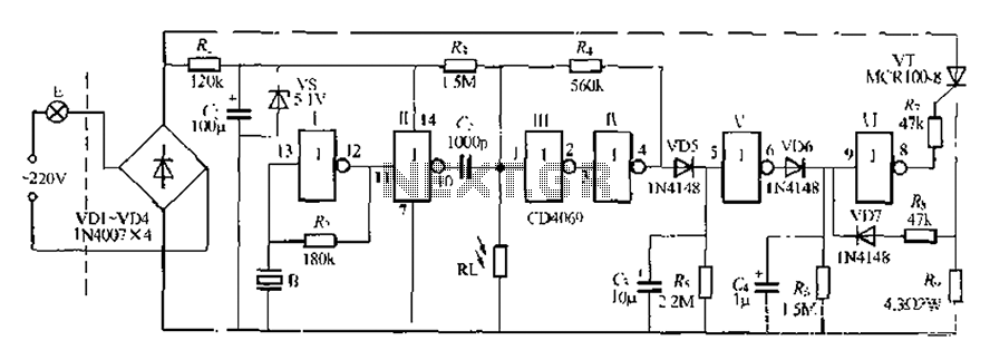
The described circuit operates as an automatic control system for lighting, utilizing a combination of sound detection and light sensing to manage illumination in stairways and walkways. The core components include a photosensitive resistor, a thyristor (VT), and a sound sensor, which together create a responsive lighting system that adapts to environmental changes.
During daylight hours, the photosensitive resistor (Ri) exhibits low resistance, leading to a low output voltage at the gate input terminal. This condition effectively turns off the thyristor, resulting in the small lamp (E) being lit. As night falls, the resistance of the photosensitive resistor increases, allowing the circuit to engage the sound detection capabilities. The sound sensor amplifies acoustic signals, generating a high output voltage that triggers the thyristor to turn on, illuminating the lighting system.
The Schmitt trigger configuration within the circuit serves to clean up the triggering signal, ensuring that only valid signals activate the lighting system while filtering out noise and transient interference. The inclusion of a resistor-capacitor (RC) delay circuit introduces a timing mechanism that prevents rapid cycling of the lights, offering a delay of approximately 2 seconds before the system resets.
Over-current protection is integrated via a resistor (R) that limits the current flowing through the thyristor when activated. If the current exceeds a safe threshold, the circuit will prevent the lamp from lighting, thus protecting the components from damage. The use of a CD4069 hex inverter IC allows for flexible circuit design, enabling further modifications and enhancements as needed.
The circuit is designed to work with incandescent bulbs rated at 60W or less. Adjustments to the resistance values within the circuit can be made to fine-tune the sensitivity of the sound detection feature, allowing for customization based on the specific environment where the circuit is deployed. Overall, this circuit offers a robust solution for automated lighting control in various applications, enhancing safety and convenience in low-light conditions. But can not speak can be a good sound, light control stairs walkway lighting cast into the confirmation, this circuit has a high immunity under Tuo can, and indeed the soft-sta rt and over-current protection. Ri.} U photosensitive resistor is low during the day resistance, gate input terminal O pin is low and a half, two inverted Yi after Kuo feet of level, vm reverse bias is turned off. In this case f JV pin output terminal that is low, thyristor VT off, a small lamp E will be lit. night Chuan RI. high resistance, collapsing in advance adjusted R, R. resistance, so O foot still in power almost 1/2Vmf J flip the circuit threshold level below this when the circuit state does not change, but it has a higher Lu wantonly trigger sensitivity control door I constitute a linear amplifier, for which the same process 51 down, when I {feel acoustic signals, ?
pin output forward moments after 7-wave (1 coupling, make O pin goes high, the circuit state flip fat cow, electric uE bright. this circuit towel door Shan, doors IV OR; composition Schmitt trigger, whose role is: can trigger signal whole shape, and eliminate interference pulses; along with R.
constitutes a level comparator, the entire electrical system can be withered throw light control, so that daylight relatively strong, the circuit can always reset at the f state, wind with 0s delay circuit, the delay time is about data shown 2js.Ri., (j constitutes a soft-start circuit, usually when the lights, feet high, C, L/allow full charge. night time there are sound, feet low, G to R. discharge discharge time is very short about 1.5s, so a feet from the high becomes low, the thyristor VT opened.
overcurrent Tuen Mun Road H VD7.R., R. composition, R is sampling and limiting. resistor, if VT opened, the lamp I: moderate power, R.r- voltage drop low enough to make VD7 turned. foot is always high, bulb point end bright until R, (3 set delay time door -.! door cho using a digital block CD4069 hex inverter IC .E should incandescent bulbs 60W or 60W or less, if E fire power circuit will indiscriminately overcurrent protection role of the white line jLi lamp goes out. decrease R, values can be adjusted tU Ji sound sensitivity twist, pregnant Kang greater resistance, higher sensitivity, and vice versa low adjust R, or R, can be changed wrestling hall light control system circuit point.
Related Circuits
Two NAND gates (Di, Dz) and a resistor (Rz) along with capacitors (C1, etc.) form an RC self-excited multivibrator with an oscillation frequency of 2.5 Hz and an oscillation amplitude of 4 V. This circuit is used as a...
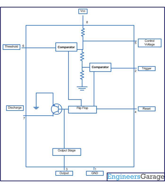
This circuit-based project demonstrates the operation of a 555 timer in astable mode to generate pulses with a time period of 0.5 seconds. These pulses can be utilized in various applications, such as blinking an LED or creating decorative...
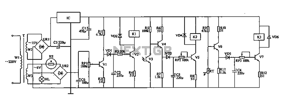
The automatic controller for a chicken coop is designed to automatically regulate light, temperature, and humidity, thereby enhancing egg production and survival rates of chickens. This device is intended for specialized poultry households in rural areas. The circuit operates...
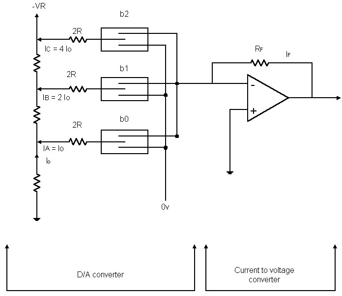
Before examining the various analog-to-digital (A-D) and digital-to-analog (D-A) conversion processes, it is useful to review the properties of each type of representation; in particular, this may help select the representation most suited to the problem at hand. An...
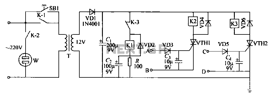
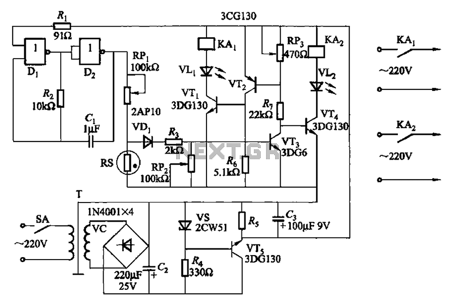
This schematic circuit features two alarm outputs controlled by a timer using thyristors. The system can be turned on or off and will shut down after the power supply is interrupted. It employs a transformer on the primary side...
This project will explain how I build my new wattmeter. This watt meter will be able to measure power from 300nW to 30W @ (0-500MHz). This wattmeter is based up on a dummy load of 50 ohm which can...
Warning: include(partials/cookie-banner.php): Failed to open stream: Permission denied in /var/www/html/nextgr/view-circuit.php on line 713
Warning: include(): Failed opening 'partials/cookie-banner.php' for inclusion (include_path='.:/usr/share/php') in /var/www/html/nextgr/view-circuit.php on line 713