
Electronic type bass equalization circuit

This electronic bass equalizer circuit is designed to enhance audio playback by allowing users to adjust the bass levels effectively while maintaining sound quality. The TL084 operational amplifier is selected for its high-speed performance, making it suitable for audio applications. The circuit's architecture includes two main sections: the high-pass filter and the band-pass filter, which work in tandem to manage low-frequency signals.
The high-pass filter, implemented with A2, is critical for eliminating unwanted sub-bass frequencies, ensuring that only desirable audio signals are processed. The corner frequency of 20Hz is a strategic choice, as it allows for the preservation of the auditory experience while preventing mud or distortion in the low end. The second-order configuration of the filter provides a steeper roll-off, enhancing the effectiveness of the equalization.
A3's role as a band-pass filter further refines the audio output by selectively amplifying frequencies around the 20Hz mark. This filter's design includes multi-port negative feedback, which stabilizes the gain and improves linearity, essential for high-fidelity audio reproduction. The 12dB per octave attenuation for frequencies below 20Hz ensures that the output remains clean and focused on the intended bass frequencies.
The bass boost network, created by resistors Rg, R1, and G, is a vital component that allows for user-adjustable enhancement of low frequencies. By providing a 3dB boost from 7Hz to 220Hz, the circuit can cater to various listening preferences and environments, making it versatile for different audio setups.
The inverting adder circuit configuration effectively combines the outputs of the high-pass and band-pass filters, ensuring that the overall audio output is balanced and smooth. This integration is crucial for maintaining audio fidelity, preventing phase issues that could arise from improper signal mixing.
Overall, this electronic bass equalizer circuit is a sophisticated solution for enhancing low-frequency audio performance, offering precise control over bass levels while ensuring high-quality sound reproduction. The careful selection of components and design considerations contribute to its effectiveness in various audio applications.Electronic bass equalizer type of two quad op amp circuit, you can use TL084 high-speed operational amplifier circuit shown in Figure 9-680 left and right channels through R1, R2 were mixed units, build a total of bass level adjustment potentiometer (for logarithmic). Al is a buffer amplifier, A2 constituting the second-order high-pass filter corner frequency of 20Hz, filtered subwoofer sound signal outside the band where o ~ and constitute a key part of the circuit - Dying sound equalization circuit oA3 constitute multiport negative feedback active second order band-pass filter, a central rate of the amount of 20Hz, 20Hz or less signal 12dB per octave attenuation. ~ And Rg, Rio, G constitute bass boost network 1 from the beginning to around 220Hz octave slope by 3dB boost bass from 7Hz Liu 2,2, OHz 30dBoRr and co-promotion with Di ~ constituting the inverting adder circuit, A2 output signal plus A3 bandpass signal, so at 20 lift increase, balanced response is smooth o
Related Circuits
A device designed to locate a mobile phone by emitting intermittent flashes and beeps, indicating the presence of an active mobile phone. This circuit activates even when the mobile phone is in silent mode, making it effective for detecting...
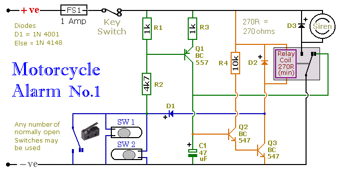
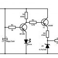
This circuit includes a timed output and an automatic reset feature. It can be manually operated using a key switch or a concealed switch. By incorporating an external relay, the circuit will automatically engage or immobilize the machine each...
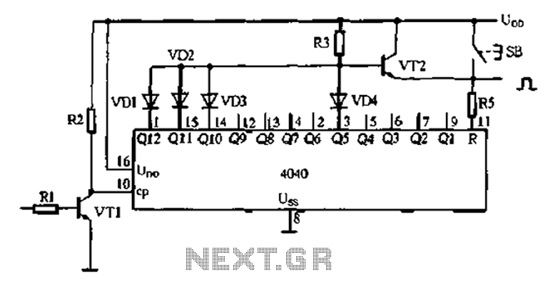
An analog electronic clock that utilizes a trigger signal for operation. An analog electronic clock typically employs a trigger signal to manage its timekeeping functions. The clock's primary components include a quartz crystal oscillator, which provides a stable frequency reference,...
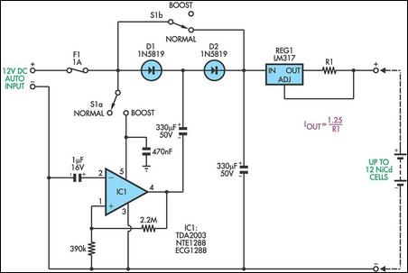
This circuit is designed to charge between one and twelve NiCd cells using a car battery. When switch S1 is in the "normal" position, it can charge up to six cells. The LM317 regulator functions as a simple current...
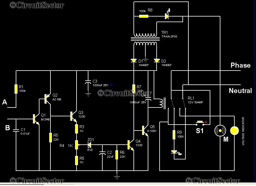
This is an automatic water tank controller designed to manage the operation of a water pump using a 12V 10A relay. When the water level in the tank creates a short circuit between points A and B in the...
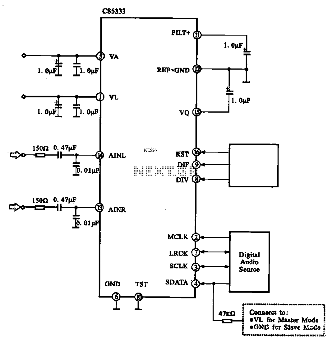
Audio A/D converter circuit configuration using the CS5333 chip, which is a high-performance 24-bit, 96 kHz stereo A/D converter commonly used in digital products. This circuit converts one or more audio signals into a digital signal for processing and...