
Water Tank Controller Circuit PCB

The automatic water tank controller circuit operates using a straightforward configuration that includes essential components: a relay, a transistor, a switch, and resistors. The relay serves as the main switching device that controls the water pump, allowing it to turn on or off based on the water level detected in the tank. The relay is rated for 12V and 10A, ensuring it can handle the load of the water pump effectively.
In the circuit, the switch S1 is used to manually initiate the pump operation. When pressed, it allows current to flow through resistor R1, which in turn biases transistor Q1 into conduction. This action energizes the relay coil, closing the relay contacts and allowing current to flow to the water pump. The pump will then operate to fill the tank.
The critical aspect of this design is the placement of terminals A and B, which serve as the water level sensors. These terminals are designed to be submerged at a predetermined level in the tank. When the water rises to this level, it creates a conductive path between A and B, effectively short-circuiting them. This condition causes transistor Q1 to remain in the ON state, which keeps the relay de-energized. Consequently, the relay contacts open, cutting off the power supply to the water pump and stopping its operation.
This automatic water tank controller circuit is an efficient solution for maintaining optimal water levels in tanks without manual intervention. Its simplicity and low cost make it suitable for various applications, including residential water systems and agricultural setups. Additionally, the use of a PCB for assembly enhances reliability and reduces the chances of wiring errors during installation. Overall, the described circuit is an effective method for automating water tank management, ensuring that the pump operates only when necessary.Here is an automatic water tank controller that controls the operation of a water pump through a 12V 10amp relay. When ever the water level of the tank short circuits the points A and B in the circuit diagram, the pump get turned off automatically.
This home water pump controller circuit is comparably simple and low cost and can be assembled easil y on a common PCB. The circuit schematic diagram of the tank controlller is given on the image. Whe the switch S1 in the circuit is pressed, a biasing will get to the transistor Q1 through resistor R1 and the relay will be turned on. So the pump connected on the relay will also switched on. We can place the terminals A and B in the upper side of the water tank. Whenever the water shortcircuits these points, the Q1 transistor will be on and the relay will cuttoff and the motor also turned off.
🔗 External reference
Related Circuits
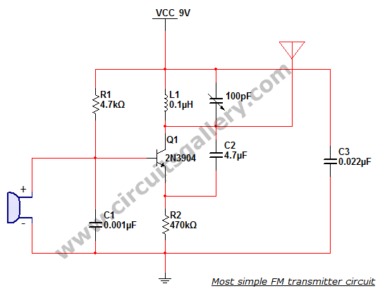
This is the simplest single transistor FM wireless transmitter circuit ever posted in CircuitsGallery. In the field of telecommunications, frequency modulation (FM) transmits information by altering the frequency of a carrier wave based on the message signal. FM utilizes...
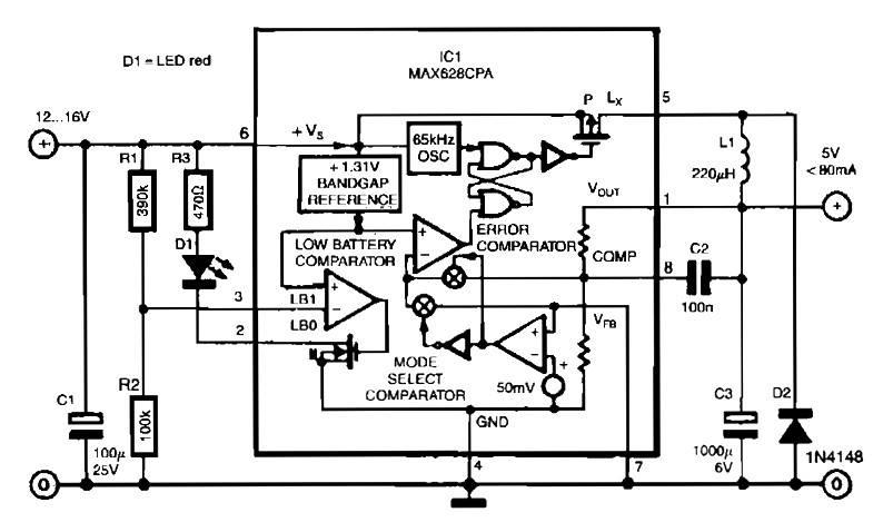
The circuit utilizes the MAX638CPA 5V CMOS Step Down Adjustable Switching Regulator IC, which converts an input voltage of 12 to 16 VDC into a stable 5VDC output. It requires only nine additional external components to complete the circuit....
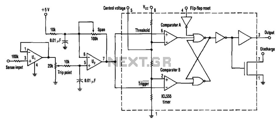
Many applications require analog signals to be sensed and digital signals to be controlled. A way to detect these points is by using a 555 timer in an unconventional configuration. This method will also add hysteresis to the circuit...
Using this low cost project, one can reproduce audio from a TV without disturbing anyone. It does not use any wire between the TV and headphones. Instead of a pair of wires, it uses invisible infrared light to transmit...
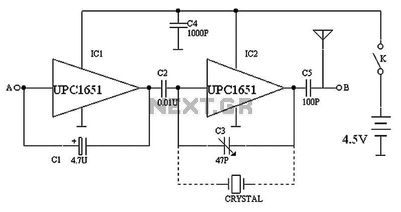
The circuit depicted in the figure includes IC1 and C1, which form a low-frequency oscillator operating at approximately 400 Hz. IC2 and C3 are configured to create a frequency oscillator around 37 MHz. The low-frequency signal is output from...
Savings on electricity bills can be achieved by utilizing alternative power sources. The photovoltaic module, or solar panel, described here can provide a power output of 5 watts. Under full sunlight conditions, the solar panel generates an output voltage...