
battery charger circuit
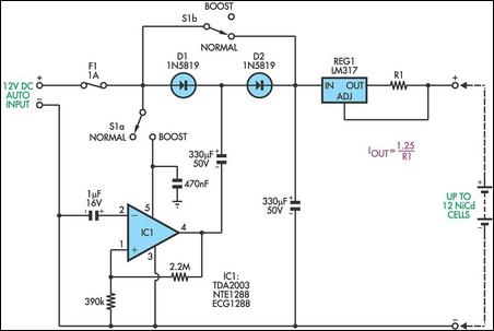
The charging circuit utilizes the LM317 voltage regulator, which is configured to operate in two modes based on the position of switch S1. In the "normal" mode, the circuit is optimized for charging up to six NiCd cells, where the current output is regulated to approximately 530mA. The resistor R1 plays a critical role in setting the output current; specifically, it is calculated to be 2.35Ω through the use of two 4.7Ω resistors in parallel, ensuring the current remains within safe limits for the cells.
When more than six cells need to be charged, the circuit transitions to "boost" mode by toggling switch S1. In this mode, the circuit powers IC1, which serves as an audio power amplifier rated at either 10W or 20W. The design incorporates positive feedback from the output pin (pin 4) back to the non-inverting input (pin 1) of IC1, allowing it to generate a square wave oscillation. This square wave is essential for the operation of the charge-pump voltage doubler, which consists of Schottky diodes D1 and D2 and a coupling capacitor of 330 µF.
The charge-pump configuration effectively doubles the voltage, producing over 20V at the input to REG1, which is crucial for charging the maximum of twelve NiCd cells. This voltage is sufficient to overcome the charging requirements of the cells, ensuring efficient and effective charging. The design emphasizes reliability and performance, making it suitable for applications where multiple NiCd cells need to be charged from a single car battery source.This handy circuit can be used to charge from one to 12 NiCd cells from a car battery. Up to six cells can be charged with switch S1 in the "normal" position. The LM317regulator operates as a simple current source, providing about 530mA when R1 = 2. 35O (two 4. 7O resistors in parallel). For more than six cells, S1 is set to the "boost" position. Th is applies powers to IC1, a 10W (or 20W) audio power amplifier. Positive feedback from its output (pin 4) to non-inverting input (pin 1) causes IC1 to act as a square wave oscillator. This square wave signal is coupled to the junction of Schottky diodes D1 and D2 via a 330 µF capacitor, forming a conventional charge-pump voltage doubler.
Over 20V (unloaded) appears at the input to REG1 - enough to charge a maximum of 12 cells! 🔗 External reference
Related Circuits
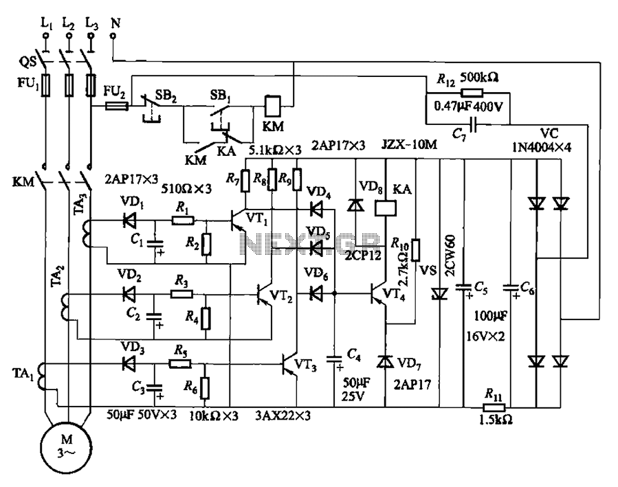
The current detection signal is obtained from three current transformers after rectification and filtering, resulting in three DC voltage outputs. These voltages are applied to transistors VT1, VT2, and VTa between the base and emitter. The signal is amplified...
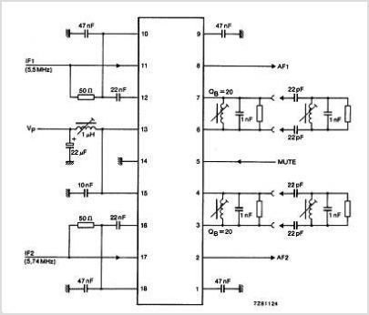
The TDA3567 is a monolithic integrated decoder designed for the NTSC color television standards. It incorporates all the necessary functions for the demodulation of NTSC signals. Additionally, it features a luminance amplifier and an RGB matrix amplifier. These amplifiers...
An integrated circuit is precisely that: an integrated circuit. These small packages combine numerous individual components to perform a specific function. They vary in shape and size depending on their complexity. They are categorized into functions such as audio,...
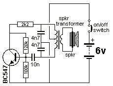
The Colpitts Oscillator is characterized by tapping the mid-point of the capacitive side of the oscillator section. The inductor can be the primary side of a speaker transformer. The feedback comes via the inductor. The Colpitts Oscillator is a type...
The above circuit is a precision voltage source and contains a temperature sensor with a negative temperature coefficient. Meaning, whenever the surrounding or battery temperature increases, the voltage will automatically decrease. The temperature coefficient for this circuit is -8mV...
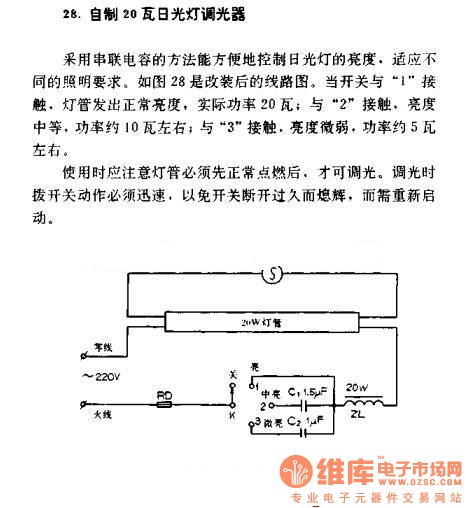
A homemade 20W fluorescent lamp dimmer utilizes a series capacitor connection to effectively control the brightness of fluorescent lamps, allowing for adaptability to various lighting requirements. In the modified circuit diagram (Figure 28), when the switch is set to...
Warning: include(partials/cookie-banner.php): Failed to open stream: Permission denied in /var/www/html/nextgr/view-circuit.php on line 713
Warning: include(): Failed opening 'partials/cookie-banner.php' for inclusion (include_path='.:/usr/share/php') in /var/www/html/nextgr/view-circuit.php on line 713