
Ratio discriminator circuit
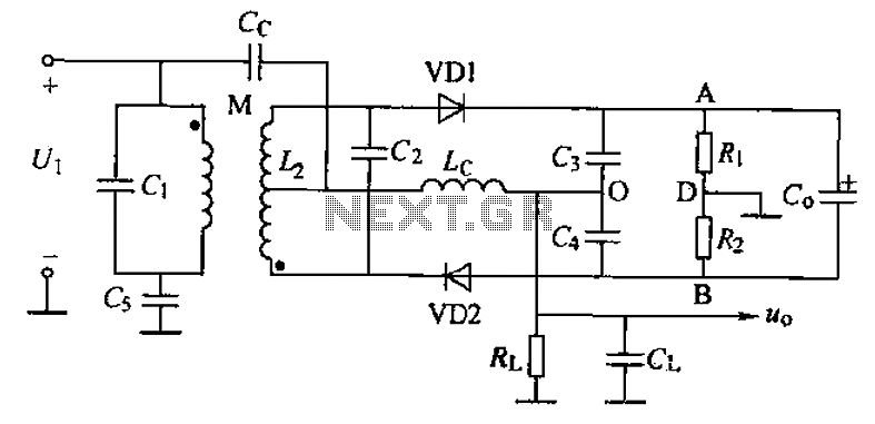
The common phase frequency detector serves as a critical component in various communication systems, enabling the extraction of frequency information from modulated signals. The mutual coupling and capacitive coupling methods allow for flexibility in design based on the specific requirements of the application. The improved mutual coupling ratio discriminator circuit, incorporating the 2AP9 diode, enhances performance by providing better sensitivity and stability.
The use of capacitors C3 and C4 in the detection process allows for effective filtering of the signal, ensuring that only relevant frequency components are processed. The strategic placement of resistors at point D facilitates the separation of output voltages, minimizing interference and ensuring clear signal representation. The connection of a large capacitor G at outputs A and B plays a pivotal role in stabilizing the output voltage during rapid amplitude changes, which is crucial in maintaining signal integrity in dynamic environments.
The inclusion of diodes in the circuit design is essential for ensuring that the output voltages from the two detectors remain in phase, allowing for coherent summation. This design choice enhances the overall reliability of the frequency detection process, making it suitable for applications requiring precise frequency tracking and phase comparison. The comprehensive design considerations taken in this circuit make it a robust solution for phase frequency detection in modern electronic systems. Common phase frequency detector can be divided into mutual coupling and capacitive coupling frequency discriminator frequency discriminator according to their coupling. Its imp roved mutual coupling ratio discriminator circuit is shown in the figure, the diode is 2AP9 2. z- phase discriminator in an AM-FM FM wavelet transform parts of the same, but there are significant changes in the detector section. To type differences are: 1) the detection of two capacitors C3 and the connection point O C4 and two resistors connected point D separate frequency discriminator output voltage two from D, E remove points.
2) at the output A, B and connected at both ends of a large capacitance G, the electrical capacity of about lOyF, because of the time (R. + R2) C circuit constant number of large, about (o.1 ~ o .2) s, so that the detection process, for more than 15Hz amplitude changes, Udc on the capacitor G remained unchanged.
3) two diodes, one diode and phase frequency discriminator in the connection in the opposite direction. So in addition to ensure that the two diodes DC path, but also makes the two detector output voltage polarity become identical.
Thus, a two detectors at both ends of the output voltage is the sum.
Related Circuits
The synchronous vibration circuit operates with a control logic that includes three primary components. An internal oscillator is initiated by a synchronization pulse, transitioning to a low state immediately after the pulse. Upon power activation, the internal circuitry undergoes...
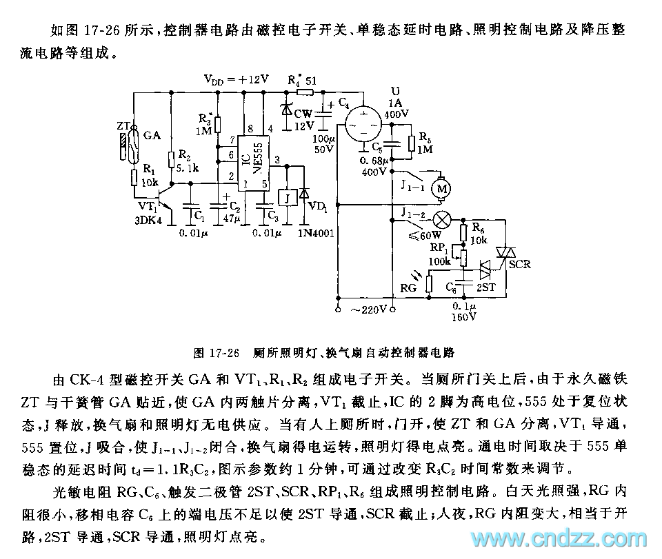
The electronic switch consists of the CK-4 type magnetic control switch and the components VT1, R1, and R2. When the bathroom door is closed, the permanent magnet ZT and the reed switch GA come into proximity, which separates the...
The schematic illustrates the subwoofer amplifier stage, specifically the pre-amplifier circuit and the signal processing circuit. Notably, it features two LM3886 power ICs from the American company NS, which facilitate BTL (Bridge-Tied Load) speaker operation at an 8-ohm impedance...
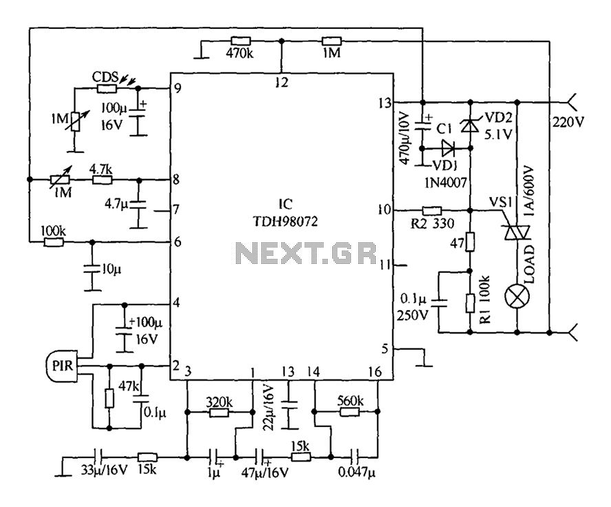
The circuit primarily consists of a new pyroelectric infrared sensor device, TDH98072, which features a special composition. This device is integrated with a control circuit characterized by simplicity, ease of adjustment, and high reliability. Additionally, the device can be...
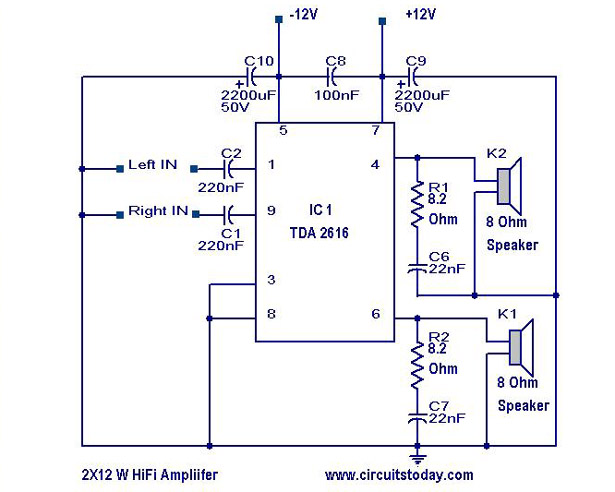
A simple Hi-Fi amplifier circuit diagram with a schematic for creating an audio amplifier, designed using the TDA 2616 integrated circuit (IC), which is a stereo power amplifier. It is suitable for use with radios, tape players, and televisions,...
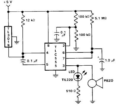
This door open alarm electronic project is designed using a linear hall effect device and a 555 timer circuit. The project utilizes the TL3103 linear hall effect device for detecting the angle of rotation. The TL3103 is positioned within...