
Electronic circuitry Dot Award
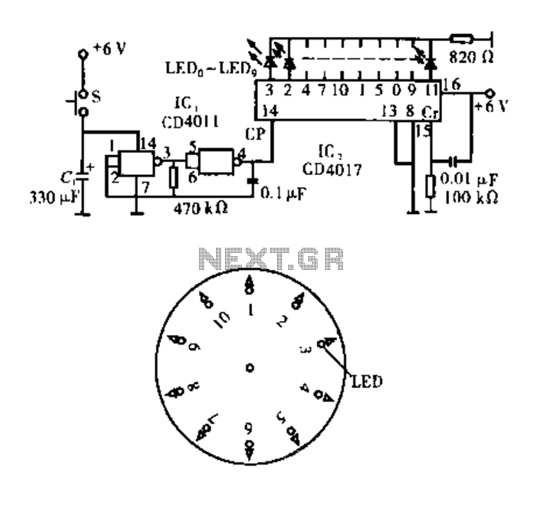
The circuit operates based on the interaction between two integrated circuits, IC1 and IC2, along with a momentary switch and a capacitor. When the button switch (S) is pressed, it initiates the charging of capacitor C1, which provides the necessary power to IC1. IC1 is designed to function as a pulse oscillator; it generates a series of pulses that begin at a high frequency and subsequently decrease in frequency over time. This behavior is crucial for creating a dynamic visual effect.
The duration of the pulse oscillation is controlled by the charging characteristics of capacitor C1 and the inherent design of IC1. Once the capacitor is charged, the oscillation continues for a predetermined time, typically exceeding ten seconds, before stopping the output pulse. This feature allows for a brief period of activity, which can be utilized for various applications, such as indicating a status or providing visual feedback.
IC2 serves a dual purpose: it counts the incoming pulses from IC1 and decodes these pulses to drive a display comprised of ten LEDs. This arrangement enables the circuit to visually represent the pulse count in a clear and engaging manner. The LED display can be configured to light up in response to the count, creating a sequence that is both informative and visually appealing.
Furthermore, the output from IC2 can be modified to slow down the flashing of the LEDs. This delay mechanism ensures that the visual feedback is not only immediate but also allows for a gradual transition, enhancing the user experience. The design of this circuit is versatile and can be adapted for various applications, including educational tools, decorative lighting, or as a component in larger electronic systems where visual indicators are required.Dot Award ; This circuit is tested and functionable. The circuit consists of two lC constituted. lC1 constitute pulse source, because it is just a momentary button switch S is closed after charging the capacitor C1 to a C1-powered, so IC1 pulse oscillation source composed only been a while (more than ten seconds) will stop the vibration. But it is the first oscillation frequency from high to low. Pulse counting, decoding so constituted by the IC2 and display driver driven ten LED, then also with the pulse IC, output and to slow down after another to stop the flashing.
Related Circuits
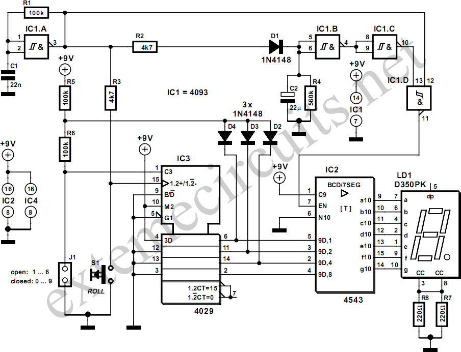
The simplicity of a traditional die makes it exceptionally difficult to create a fully equivalent electronic version, primarily because an electronic version necessitates a power supply and a collection of electronic components that occupy a significantly larger volume than...
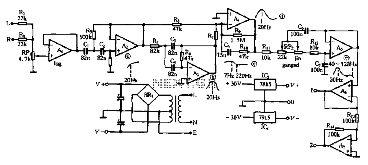
This electronic bass equalizer circuit utilizes two quad operational amplifiers, specifically the TL084 high-speed operational amplifier. The circuit includes left and right channels that are mixed through resistors R1 and R2, and features a total bass level adjustment potentiometer...
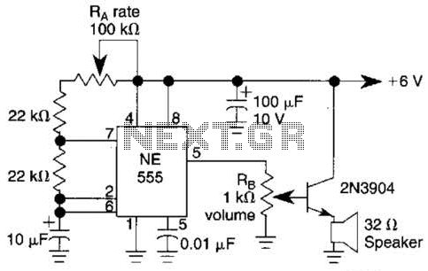
Ra sets the rate while RH sets the volume of clocks in the speaker. The 555 is configured as a low frequency oscillator. The circuit is powered by a 6 V battery. The circuit utilizes a 555 timer IC configured...
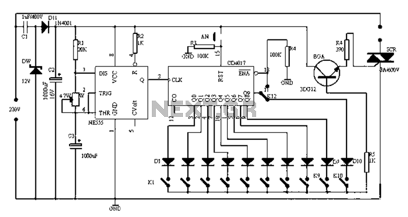
Figure 1-1 illustrates a general-purpose timer capable of timing intervals ranging from 5 minutes to 18 hours. The timing cycle can be adjusted to span from 5 minutes to 20 hours, with a maximum control time of 18 hours....
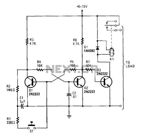
Transistors Q1 and Q2 form a flip-flop configuration, while Q3 operates a reed relay. Upon initial power application to the circuit, Q1 and Q3 are in a conducting state, whereas Q2 remains off. A momentary closure of switch S1...
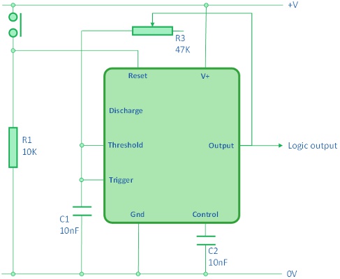
The 555 astable board utilizes a 555 timer configured in astable mode, producing a square wave or alternating high and low signals. The frequency of the signal is determined by capacitor C1 and variable resistor R3. This design is...