
Three motor control circuit start and stop sequence requirements
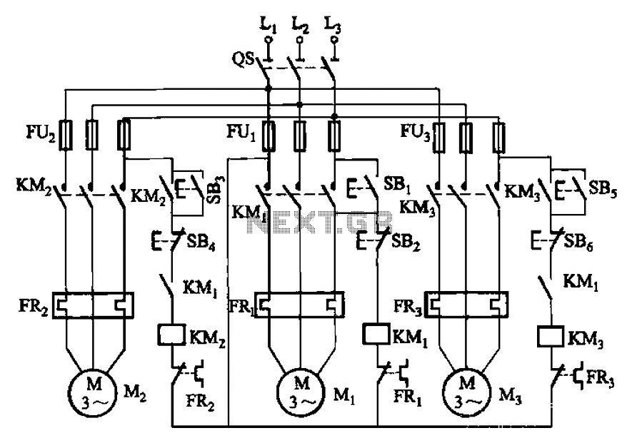
The circuit utilizes a sequential control mechanism to manage the operation of multiple motors. Motor M1 acts as the primary motor, and its activation is critical for the operation of motors M2 and M3. This configuration ensures that the motors are interdependent, where the starting of M2 and M3 is contingent upon the operational status of M1.
The shutdown sequence is designed to prioritize the stopping of motor Mz, which can be halted independently of the other motors. This feature provides flexibility in controlling the system, allowing for maintenance or safety protocols to be enacted without affecting the entire circuit.
The inclusion of switch SB2 serves as a manual control point for stopping motor M1. When SB2 is activated, it triggers a response that leads to the immediate shutdown of motors M2 and M3, thereby ensuring that all motors are synchronized in their operation and shutdown processes.
This design is particularly useful in applications where motors are part of a larger system, such as in conveyor belts or assembly lines, where the coordinated operation of multiple motors is essential for efficiency and safety. The circuit can be further enhanced with additional features such as overload protection, thermal sensors, or automated control systems for improved performance and reliability. Circuit shown in Figure 3-89. After starting the motor Mi can guarantee, it allowed the other two to start the motor. Shutdown, power motivation Mz, can first stop, but as long as the motor M1 stop (press SB2), the motor M2, M3 also stop.
Related Circuits
This project involves a simple metal detector circuit that is easy to construct using a single transistor and a few additional components. The circuit operates as a Colpitts oscillator, broadcasting on the AM band. To use it, place a...
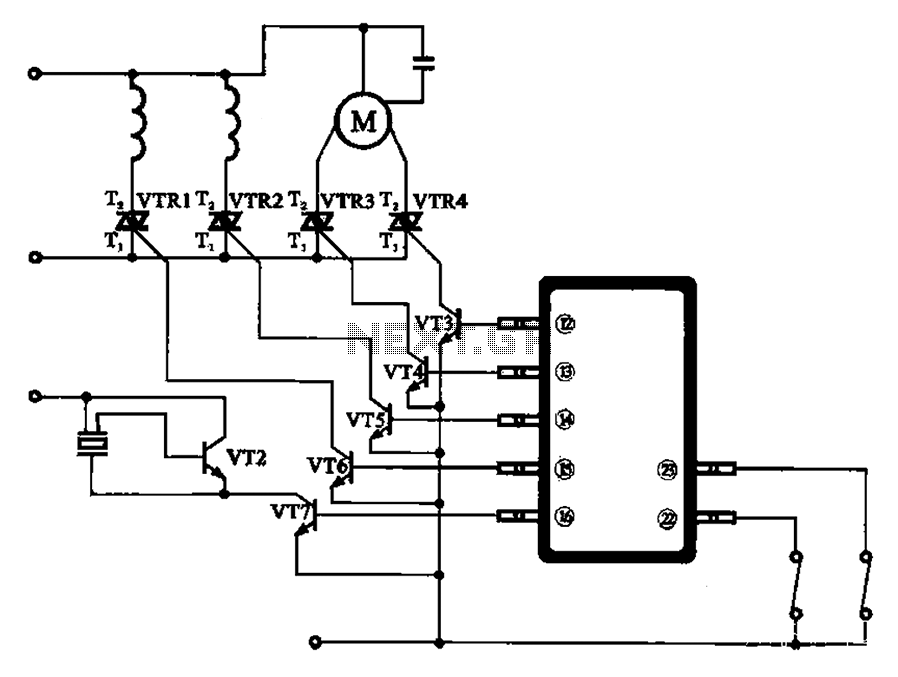
The schematic for the automatic washing machine motor driver outlines the motor drive circuit for the Narcissus XQB30-III-type washing machine. The control circuit comprises four Triacs, four drive transistors, and a control chip. This setup allows for the activation...
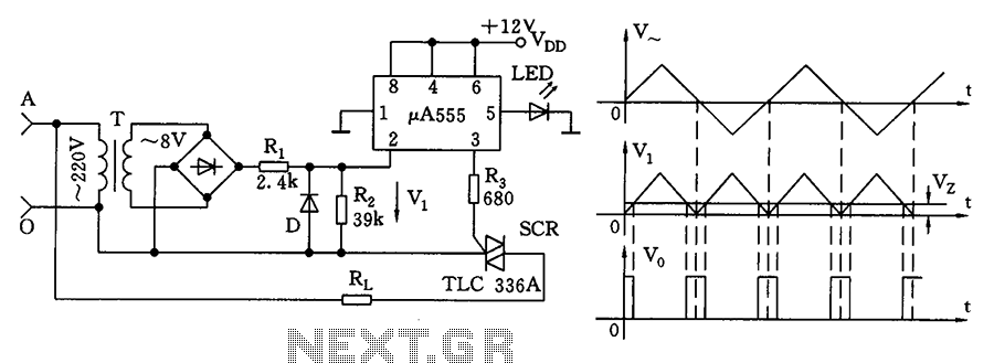
The zero volt switching circuit generates a trigger pulse at the zero crossing of the AC voltage. To facilitate this, the zero crossing of the 555 limit comparator is connected to a single form, with the comparison voltage set...
When the water level is below the steel rods, there is no contact between the metal can and the rods, which are supported by a small insulated wooden board. The circuit built around IC1 draws no current, resulting in...
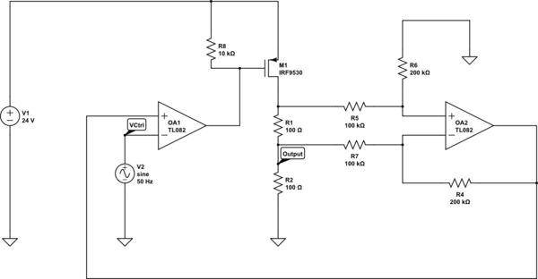
Create a 0-25 mA current limiter using a control voltage input of 0-5 V to regulate the current through a resistive load (R2), which can vary between 0-200 ohms. The O2 operational amplifier (op-amp) functions as a differential amplifier...
This circuit is a conventional Pierce type oscillator that utilizes a JFET. It employs fundamental mode crystals and demonstrates good performance and reliability when a low noise JFET is used. The feedback is regulated by the capacitance C1, which...