
Electronics Motor Controller AC Motor
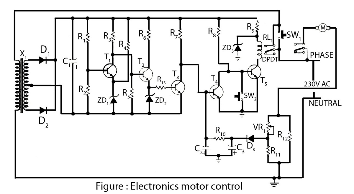
The electronics motor control circuit operates without the need for integrated circuits, making it a straightforward design suitable for basic applications. This circuit typically utilizes discrete components such as resistors, capacitors, diodes, and transistors to manage the operation of an AC motor.
A common configuration for such a circuit includes a triac or a thyristor, which serves as the primary control element. The triac is responsible for switching the AC voltage to the motor on and off, thereby controlling its speed and direction. The gate of the triac can be triggered by a control circuit, which may include a variable resistor (potentiometer) to adjust the firing angle, allowing for speed control.
The circuit may also incorporate a zero-crossing detector to ensure that the triac is triggered at the appropriate point in the AC waveform, minimizing electrical noise and reducing stress on the motor. Additionally, snubber circuits can be included to protect the triac from voltage spikes caused by inductive loads, ensuring reliable operation.
In terms of the circuit diagram, it typically displays the connections between the AC power source, the control components, and the motor. The diagram should clearly indicate the positions of the triac, control resistors, and any protective components. Proper labeling of each component is essential for clarity and ease of understanding.
Overall, this electronics motor control circuit is a practical solution for controlling AC motors in various applications, ranging from small appliances to industrial machinery, while maintaining simplicity in design.Electronics motor control is a simple circuit made without IC.electronics control of AC motor.circuit diagram with description of electronics motor controller. 🔗 External reference
Related Circuits
Foggers used to generate fog and smoke effects operate by heating a special fogger fluid. They consist of a heating element that is maintained at the correct temperature using a thermostat. When the operator wants to generate smoke, they...
To understand how the 74AC14 PWM circuit functions, it is essential to focus on the schematic section that includes the trimpot, diodes, capacitor, and the first inverter logic gate. Initially, when power is applied to the circuit, the capacitor...
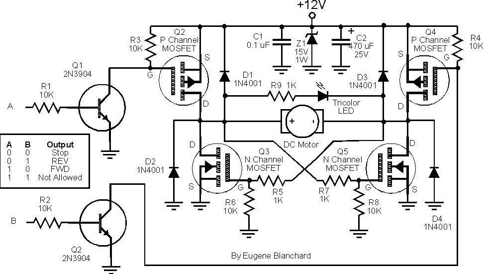
At 9 volts, the maximum stalled current of the motor types intended for use will be 700 mA. The selection of appropriate MOSFETs is crucial, particularly regarding their ratings for current and voltage handling. However, there are concerns about...
This circuit automatically controls the headlight of a motorcycle, turning it on and off independently of the light and ignition switches, as long as the battery is fully charged. The initial stage employs a 220-ohm resistor and ZD1 to...
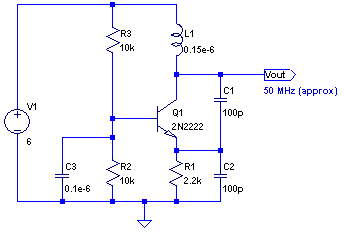
The core of any transmitter is typically an oscillator circuit, and in simple transmitters, such as QRSS devices, a crystal is often used. Frequency adjustment is achieved by modifying the capacitance to ground on one of the crystal's legs....
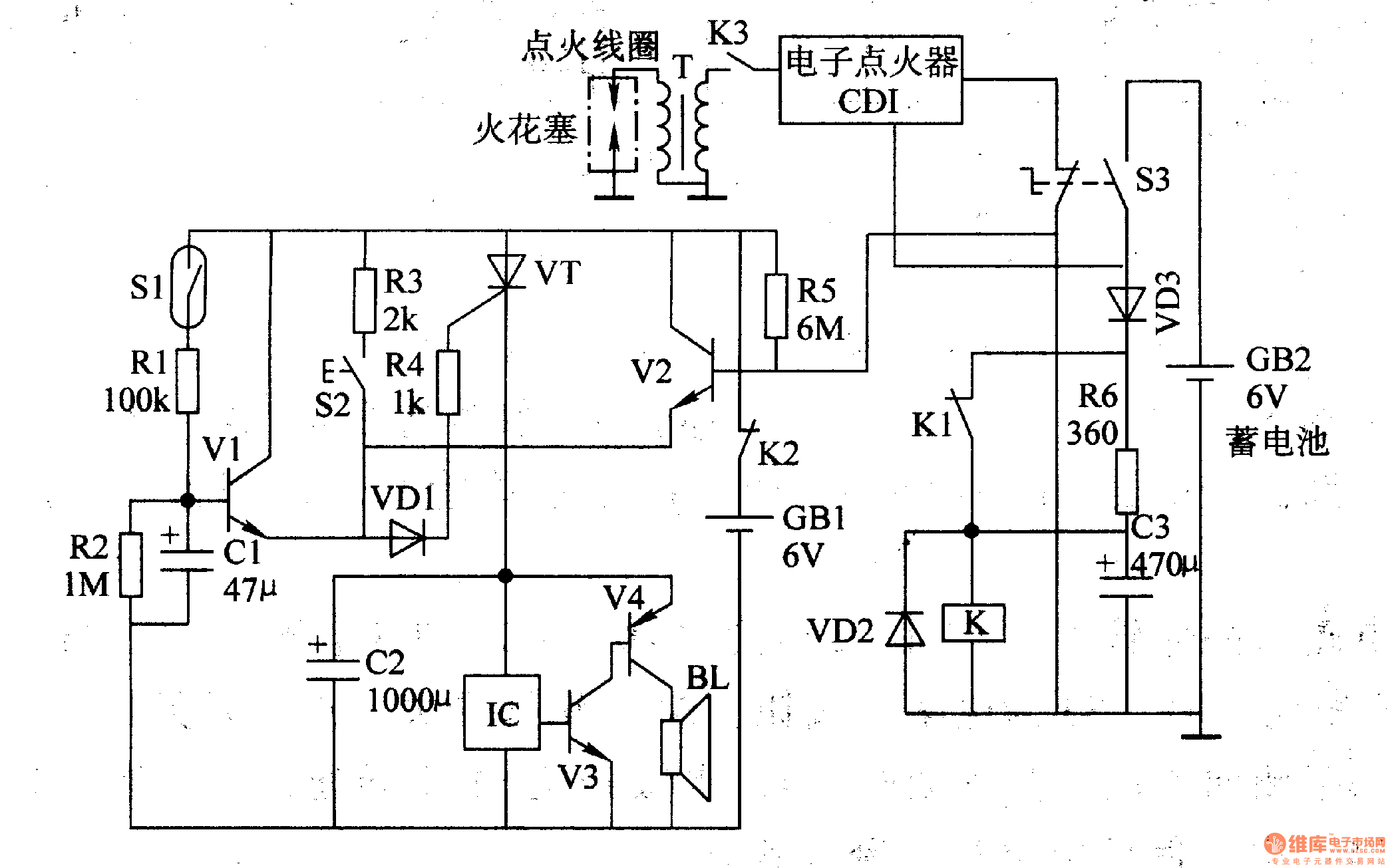
The multi-function motorcycle anti-theft alarm discussed in this article is suitable for anti-theft applications for all two-wheel motorcycles. The motorcycle anti-theft alarm circuit consists of a mobile delay alarm circuit, an ignition switch ground wire break alarm circuit, and...
Warning: include(partials/cookie-banner.php): Failed to open stream: Permission denied in /var/www/html/nextgr/view-circuit.php on line 713
Warning: include(): Failed opening 'partials/cookie-banner.php' for inclusion (include_path='.:/usr/share/php') in /var/www/html/nextgr/view-circuit.php on line 713