
Microcontroller Clocking a Transmitter?

The described transmitter design revolves around the utilization of a microcontroller, specifically the Atmel ATTiny2313 AVR, which integrates oscillator functionality that can be adapted for RF transmission. The oscillator circuit, a fundamental component of the transmitter, is tasked with generating a stable frequency signal, typically achieved through a crystal oscillator configuration. The ability to modify the capacitance connected to the crystal allows for fine-tuning of the output frequency, which is critical for accurate RF transmission.
In this design, the pins designated for the crystal (pins 4 and 5) facilitate the connection of an external crystal oscillator, while pin 6's CKOUT feature offers the potential to output a clock signal. The nature of this signal—whether it is a sine wave or a square wave—has significant implications for the performance of the transmitter. A sine wave output would be ideal for RF applications, as it is less prone to distortion and more efficient for transmission. Conversely, a square wave would require additional filtering to smooth the signal before transmission.
The proposal to implement a variable capacitance mechanism through a reverse-biased LED introduces an innovative approach to dynamically adjust the oscillator frequency. This method would allow for real-time frequency modulation, which could enhance the versatility of the transmitter in various applications. The integration of such a feature within a single microcontroller chip simplifies the overall circuit design, reducing the number of components required and potentially lowering costs.
Testing of the prototype has indicated that the transmitter is capable of generating RF signals strong enough to be detected by a nearby receiver. However, further investigation is needed to ascertain the precise characteristics of the output waveform and the overall power output. This information is crucial for determining the efficacy of the design and its suitability for long-distance transmission applications. Additional measures, such as incorporating a preamplifier or low-pass filter, may be necessary to optimize the signal quality and ensure reliable transmission over extended ranges.The core of any transmitter is usually an oscillator circuit, and in simple transmitters (i. e. , QRSS devices), it`s often a crystal. Frequency adjustment is accomplished by adjusting capacitance to ground on one of the crystal legs. Simple oscillators such as the Colpitts design (based on an NPN transistor) are often used. (pictured) However in my quest to design a minimal-case long-distance transmitter, I`m trying to think outside the box. Although it`s relatively simple, that`s still several parts just to make an oscillating sine wave from a crystal. The result still has to be preamplified before sending the signal to an antenna. I`m starting to wonder about the oscillator circuitry inside a microcontroller which has the ability to be clocked by an external crystal.
For example, take the pinout diagram from an Atmel ATTiny2313 AVR: : See how pins 4 and 5 allow for a crystal, and pin 6 has a CKOUT feature I`m still not sure exactly what the waveform of its output looks like. The datasheet is almost intentionally cryptic. About the only thing I`ve been able to discover from the Internet is that it`s sufficient to clock another microcontroller.
However, if it`s an amplified sine wave output, how cool is it that it might be able to produce RF at the same frequency at which it`s clocked Taking it a step further, I wonder if I could write code for the microcontroller to allow it to adjust its own clock speed / frequency output by adjusting capacitance on one of the legs of the crystal. A reverse-biased LED with variable voltage pressed against it from an output pin of the microcontroller might accomplish this.
How cool would this be a single chip transmitter and frequency-shifting keyer all in one Just drop in a crystal of your choice and BAM, ready to go. Believe it or not I`ve tested this mildly and it`s producing enough RF to be able to be picked up easily by a receiver in the same room, but I`m still unsure of the power output or the waveform.
If the waveform is an amplified sine wave I`m going to pass out. More likely it`s a weak sine wave needing a preamplifier still, or perhaps even amplified square waves in need of lowpass filtering 🔗 External reference
Related Circuits

Introduction The ignition timing lights commonly used range from simple neon to complex units. Neon timing lights have a drawback due to their low light output, necessitating operation in subdued lighting. This presents a safety hazard, as users tend...
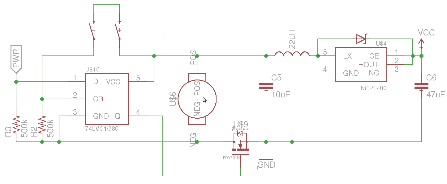
The objective is to control the power to a load, specifically an 8051-based microcontroller (uC), using two switches. When the uC is powered on, it sets the PWR pin high. Upon pressing the switches again, pin 4 of the...
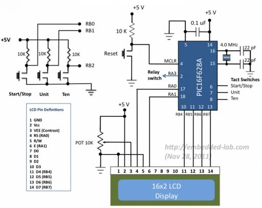
A source code for a simple PIC-based digital timer is provided. The hardware for the project is not available; however, it will be demonstrated using a DIY PIC16F628A breadboard module and I/O board. The complete circuit diagram and firmware...
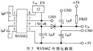
The widespread application of Flash technology in microprocessors has led to significant advancements in the development and utilization of one-chip computers. Designers have transitioned from traditional in-circuit emulators (ICE) and JTAG interfaces to more cost-effective and user-friendly development methods....

In 1991, there was significant interest in a specific display technology that was difficult to find locally and expensive to import. Currently, this technology has become widely available and is considered obsolete due to the affordability and accessibility of...
This ISP Programmer can be utilized for in-system programming or as a standalone SPI programmer for Atmel ISP programmable devices. The programming interface is compatible with STK200 ISP programmer hardware, allowing users of STK200 to also use the software...