
Fogger controller
The circuit components are as follows:
- R1: 2.2 kΩ
- R2: 220 kΩ potentiometer
- R3: 4.7 kΩ
- R4: 820 Ω
- R5: 470 Ω
- D1: 1N4007
- D2: 1N4148
- D3: 1N4007
- D4: RED LED
- C2: 220 µF, 25V
- C3: 470 µF, 16V
- C4: 22 nF
- IC1: LM555 timer
- RELAY1: Relay with 12V coil and 250V, 4A contacts
- SW1: 250V, 4A switch
- SW2: General purpose low voltage switch, rated for at least 1A current
- GLIMM: GLIMM lamp with internal current limiting resistor (Rx) for 230V (panel light)
- CON: Male 3-pin IEC mains connector
This circuit design allows for effective control of fog generation, providing a versatile solution for users seeking to enhance their fog machine's functionality.Foggers used to generate fog and smoke effects operate by heating a special fogger fluid. They consist of a heting element which is kept in the right temperature using a thermostat. When the operator want to generate smoke, he/she presses the controller button which starts the pump which pumps fog fluid to the heating element. When smoke fluid ent ers the heating element, in starts to evaporate and produce smoke. Cheap foggers usually come with only a simple one button controller. This controller is useful for smoke starting smoke effects on user request, but is not very useful if you want to keep up a constant level of fog on the room. This is where more expensive foggers come to play, because they come usually with a controller which allows you to generate fog at some slow constant adjustable rate.
If you happen to own a cheap smoke machine and happen to want this kind of functionally only found on expensive models, the circuit shown on this web page might turn to be useful to you. SUPERSTAR FZ-920 SMOKE MACHINE uses 3 pin IEC connector for the fogger remote controller. This kind of connector is used on many computer equipments for connecting grounded power to the equipment.
In this application this connector is used in quite nin-traditional way. The following circuit diagram shows the circuit diagram of the remote controller which came with the fogger: But anyway that was ho the original product was designed. If I were the redigned of the smoke machine, I would have done the thing a little bit differently. If you want more information on the insides of the Superstar FZ-920 smoke machine, take a look at my crude drawing of the circuits inside FX-920 smoke machine.
To make this circuit remotely controllable, all I had to do was to add relay on parallel with the existing button on the controller and make a circuit which controls that relay. NOTE: The wiring of the controllers of the smoke machines can vary from manufacturer to manufacturer.
The controller of your smoke machine might be entirely differently wired and might even use different type of connector. When the power is connected to the circuit by turning on SW2, RELAY1 get energized for the time it get for it to load C3 through R1 and R3.
After that the relay get de-energized, C3 gets discharged through R2 and R4. The setting of R2 determines the discharge time which can be up to 1 minute. After C3 is discharged, the releay is activated. C3 charging starts again. The charging of C3 take around 2 seconds. After that relay is de-energized and C3 discharge starts again. Every time the relay is energised, the smoke machine is set to push out smoke. The time it puts out smoke is around 2 seconds, which was adequate to put out enough smoke fluid that the smoke machine puts out smoke for a brief amount. The iime between the smoke output is adjustable from practically constant smoke output to one minute pause between brief bursts of smoke.
R1 2. 2 kohm R2 220 kohm potentiometer R3 4. 7 kohm R4 820 ohms R5 470 ohms D1 1N4007 D3 1N4148 D3 1N4007 D4 RED LED C2 220 uF 25V C3 470 uF 16V C4 22 nF IC1 LM555 RELAY1 Relay with 12V coil and 250V 4A contacts SW1 250V 4A switch SW2 General purpose low voltag switch, at least 1A current rating GLIMM GLIMM lamp with internal current limiting resistor (Rx) for 230V (panel light) CON Male 3 pin IEC mains connector 🔗 External reference
Related Circuits
I have had this project hanging around for ages and have tried to submit it for publication without much enthusiasm so I will make everything available here for the individual constructor. The complete Pascal source code for the compiler...
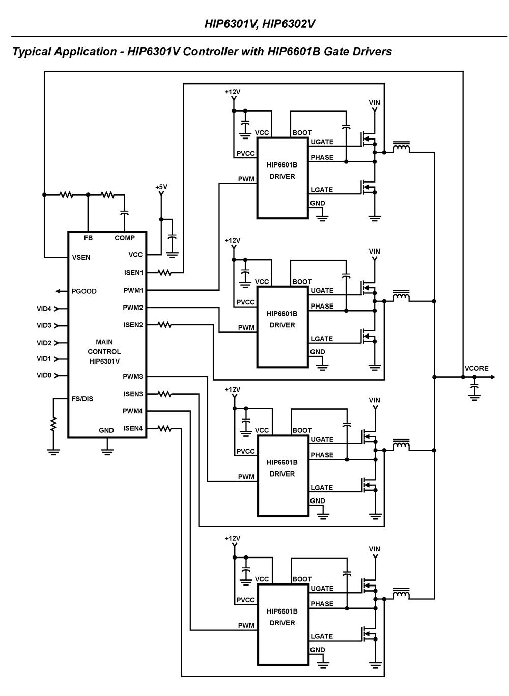
The HIP6301V and HIP6302V control the microprocessor core voltage regulation by driving up to four synchronous-rectified buck channels in parallel. The multiphase buck converter architecture employs interleaved timing to increase ripple frequency and minimize input and output ripple currents....

Combining armature resistance cancellation through positive current feedback with a motion-reversing H-bridge circuit topology introduces an innovative approach to DC servo motor speed control. The integration of armature resistance cancellation in DC servo motors is a significant advancement in enhancing...
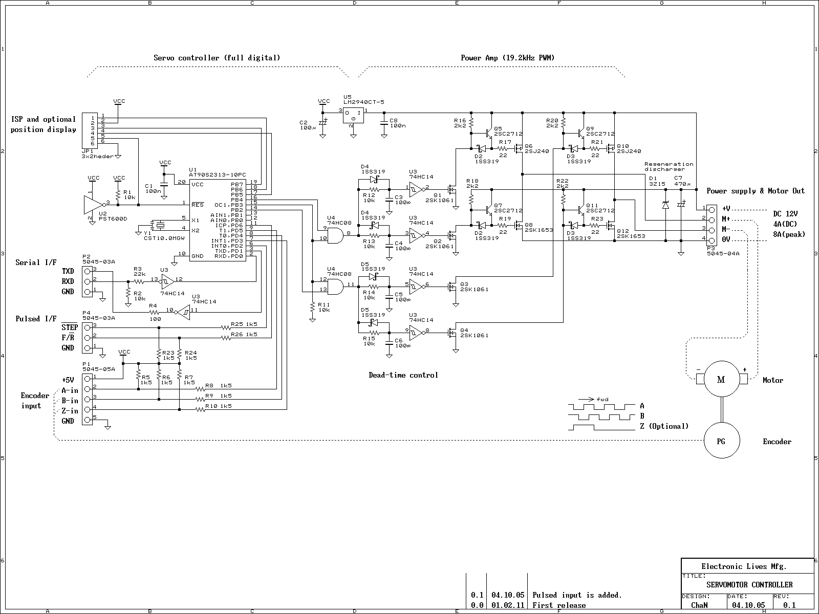
This is an experiment on the closed loop DC servomotor control system (SMC). It will be able to be used for practical use with/without some modifications. The closed loop servo mechanism requires real-time servo operations, such as position control,...
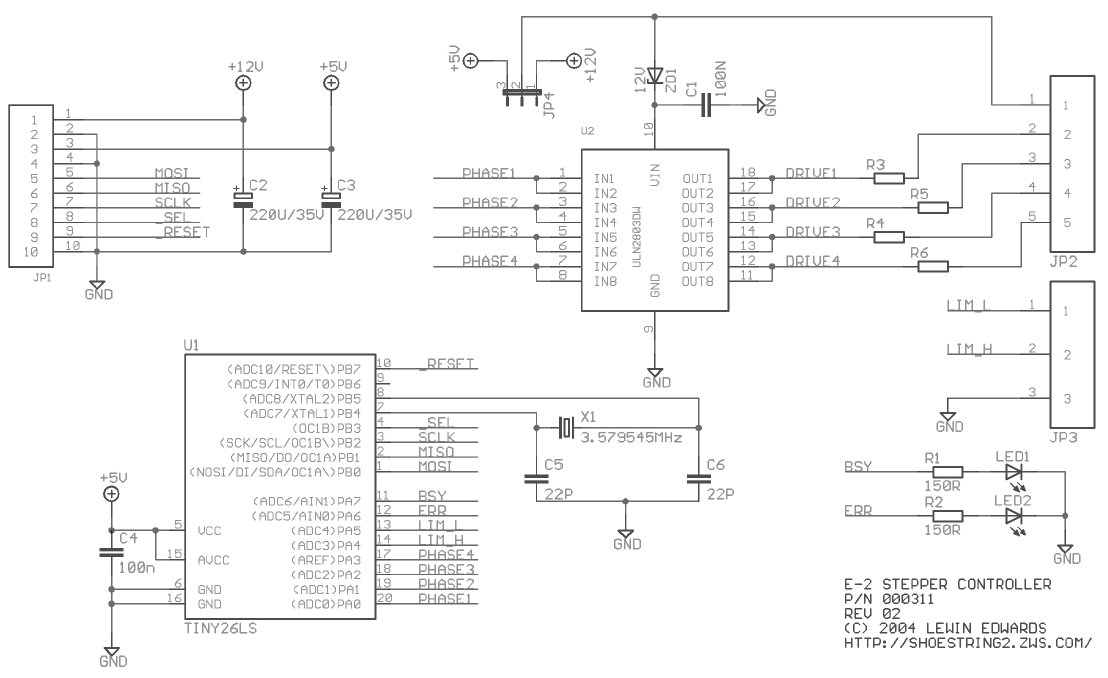
Stepper motors are beneficial for low-speed, intermediate-torque drive and positioning applications, especially where precise sub-revolution rotor position control is required. These motors are frequently utilized to drive the reels of electromechanical slot machines, position floppy disk drive heads, operate...
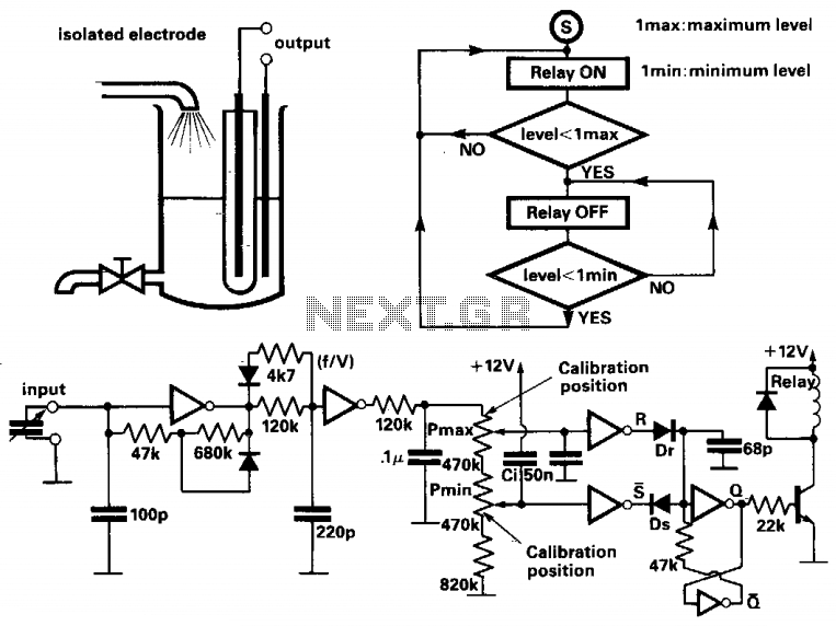
This circuit controls the liquid level in a tank using a bang-bang controlled electrical pump. The liquid level is measured by a capacitive level meter. The first inverter functions as a capacitance-to-frequency converter, operating as a Schmitt oscillator, where...