
the design of the radar for back running vehicle of MSP430

The radar system's hardware architecture centers around the MSP430F2274 microcontroller, supported by peripheral circuits including ultrasonic transmission and reception circuits, an acousto-optic alarm circuit, a communication interface, and a keyboard-LCD interface. The system's block diagram illustrates the interconnection of these components, highlighting the efficient design that contributes to the overall functionality of the reversing radar system. The MSP430F2274's low power consumption and versatile features make it an ideal choice for this application, enabling effective range finding and obstacle detection in a compact and cost-effective package.It is developed that the ones that assist driving system intelligent improvement and car electronic system that demand to the car as people are networked, new radar for back running vehicle should can serial range finding and reveals the distance of obstacle, and have communication functions, can send the data to the bus line of car. The past radar for back running vehicle designs components and parts used to be more, the function is relatively simple too. The radar for back running vehicle on the basis of the new high performance ultra low power consumption one-chip computer MSP430F2274 that this text introduces can remedy the deficiency of the past products. The overall design system of system adopts the ultrasonic range finding principle. The ultrasonic range finding instrument is generally made up of projector, receiver and part of signal processor three.
While working, the ultrasonic transmitter sends out the supersonic pulse, the ultrasonic receiver receives and meets the backward wave that obstacles reflected back, measure supersonic wave and reflect the time to return from launching to meeting obstacles accurately, according to the ultrasonic propagation velocity, can calculate the distance of obstacles. As a non-contact type detection mode, supersonic wave have the intersection of air and the intersection of propagation attenuation and light, reflecting capacity and the intersection of penetrability and better characteristic.
Ultrasonic range finding does not is influenced by light and sleet fog, bes simple in construction, makes convenient and cost low grade advantage within the range of close quarter. The high-performance one-chip computer combines ultrasonic range finding, can realize the powerful radar for back running vehicle easy to use.
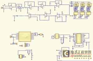
16 one-chip computer MSP430F2274 power consumption of TI Company are extremely low, resources are abundant on one, utilize JTAG interfacing at the same time, can to the intersection of flashing memory and convenient programming on the scene, benefit staging of software, very suitable as radar system of roll back microcontroller. The block diagram of the radar system of roll back is shown as in Fig. 1. System block diagram of radar for back running vehicle of Fig. 1 The systematic design system of the hardware regards MSP430F2274 microcontroller as the core, the peripheral circuit is made up of ultrasonic transmitting circuit, ultrasonic receiving circuit, acoustooptic alarm circuit, communication interface circuit, keyboard LCD circuit five part, introduce one by one as follows.
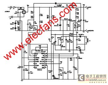
Roll back radar system top management circuit diagram of Fig. 2 The top management circuit diagram of the system is shown as in Fig. 2. MSP430F2274 chosen in this system has 32Kb flashing memory and 1Kb RAM on-chip, so needn`t expand the memorizer outside! Outer 32. 768kHz bestirs oneself brilliantly as the clock source of CPU inactive state Basic-Timer, serves as vehicle carried clock of the system at the same time.
The ones that assist driving system intelligent rise and car electronic system that require to the car with people are networked develop, new radar for back running vehicle should can serial range finding and reveals the distance of obstacle, and have communication functions, can send the data to the bus line of car. The past radar for back running vehicle designs components and parts used to be more, the function is relatively simple too.
The radar for back running vehicle on the basis of the new high performance ultra low power consumption one-chip computer MSP430F2274 that this text introduces can remedy the deficiency of the past products. The overall design system of system adopts the ultrasonic range finding principle. The ultrasonic range finding instrument is generally made up of projector, receiver and part of signal processor three.
While working, the ultrasonic transmitter sends out the supersonic pulse, the ultrasoni 🔗 External reference
Related Circuits
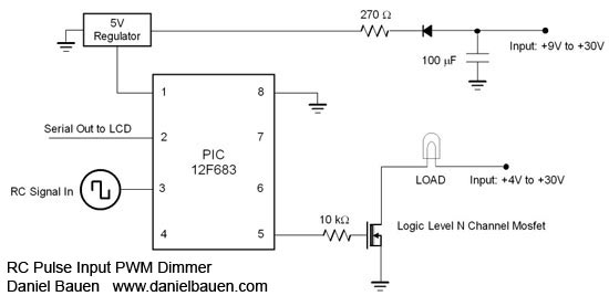
A PIC12F675 microcontroller can switch up to five outputs sequentially using a standard Remote Control pulse input ranging from 1 to 2 ms. While any RC channel input can be utilized, it is particularly effective when paired with rotary...
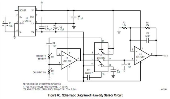
If a sensor is resistive, an alternating current (AC) is equivalent to pulsed direct current (DC), and the sensor will degrade based on the root mean square (RMS) value of the AC signal. Applying 1V AC RMS is effectively...
A walkie cardiotachometer has been designed to replace the traditional method of measuring heart rate using a pulse auscultator. This device is user-friendly and consists of three main components: signal collection, data processing, and an LED display along with...
This is an efficient flyback driver for modern cylindrical rectified television flybacks. Many sites do not provide circuits for driving these transformers; they simply state that they are ineffective. However, this circuit has been built and tested, focusing on...
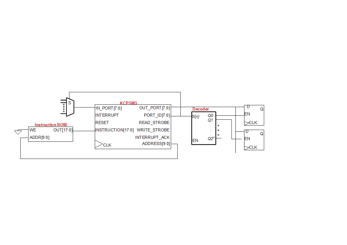
A small digital design utilizes a Xilinx Picoblaze softcore processor. Creating acceptable quality schematics has proven to be frustrating and time-consuming. Previous attempts to integrate existing schematics from LTSpice or Eagle into the documentation yielded unsatisfactory results, appearing fuzzy...
The FAN4810 operates as a continuous conduction mode (CCM) power factor correction (PFC) controller. It features an internal safety detection mechanism that prevents circuit malfunction due to component damage. The device has a power-handling capability of up to 1A,...