
project Huminator
To create a power patch cable connecting the output of the Huminator to a pedal, two 2.1mm DC plugs and a length of two-conductor wire are required. The two-conductor wire should be soldered to each of the plugs to complete the setup. Afterward, connect a 9-volt AC/DC adapter to the input. Subsequently, use a 2.1mm DC to DC patch cord to connect the output of the Huminator to the pedal, effectively eliminating unwanted hum.
The circuit described involves a basic power distribution setup for pedals, commonly used in audio applications. The positive voltage is supplied through the orange lines, while the yellow lines serve as the ground reference. The use of a perfboard or circuit board is recommended for organizing connections and ensuring reliability. Soldering is the preferred method for establishing connections due to its durability and low resistance.
The construction of the power patch cable is straightforward. The two 2.1mm DC plugs are standard connectors used in many musical devices. The two-conductor wire should be selected based on the current requirements of the connected devices, ensuring it can handle the necessary load without overheating. Proper soldering techniques should be employed to avoid cold joints, which can lead to intermittent connections.
Verification of the DC power jacks is crucial. A multimeter can be utilized to ensure that the polarity is correct and that the connections are secure before soldering. This step is vital to prevent damage to the pedals or the Huminator due to incorrect wiring.
Overall, this circuit design is effective for powering pedals in a guitar or audio setup, providing a reliable source of power while minimizing noise interference. The tip-negative standard is widely accepted in the industry, ensuring compatibility with most pedals. Following these guidelines will result in a well-functioning power distribution system for audio applications.The orange lines indicate the positive voltage and the yellow lines indicate the negative voltage, also known as ground. You can do the wiring by soldering components directly to wires, or use a small bit of perfboard/circuit board.
To ensure this thing actually works for you, be sure to check the connections on the DC power jacks before you solder them. Remember that the standard for pedal powering is tip-negative. To make a power patch cable to go from the output of the Huminator to your pedal, get two 2. 1mm DC plugs, and a length of two-conductor wire. Solder the two-conductor wire to each of the plugs and you`re ready to go. Plug your 9 volt AC/DC adaptor into the input. Then plug a 2. 11mm DC to DC patch cord into the output of the Huminator and then into your pedal. No more hum! 🔗 External reference
Related Circuits
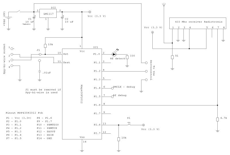
The timer generates a basic period (for instance, 20 ms), and with certain associated variables, it is possible to activate an I/O pin to produce a signal. By utilizing an 8-bit variable, the generated frequency can be divided into...
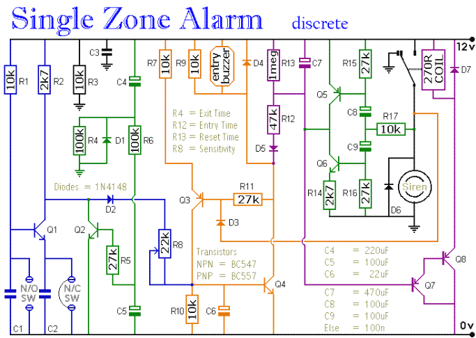
The circuit includes automatic entry and exit delays, a timed bell cut-off, and a system reset feature. It accommodates both normally open and normally closed switches, making it compatible with common input devices such as pressure mats, magnetic reed...
To manufacture large quantities of products, a manufacturing system or process is essential. This process can be categorized as either open-loop or closed-loop. In an open-loop system, variables are controlled manually, whereas in a closed-loop system, they are controlled...
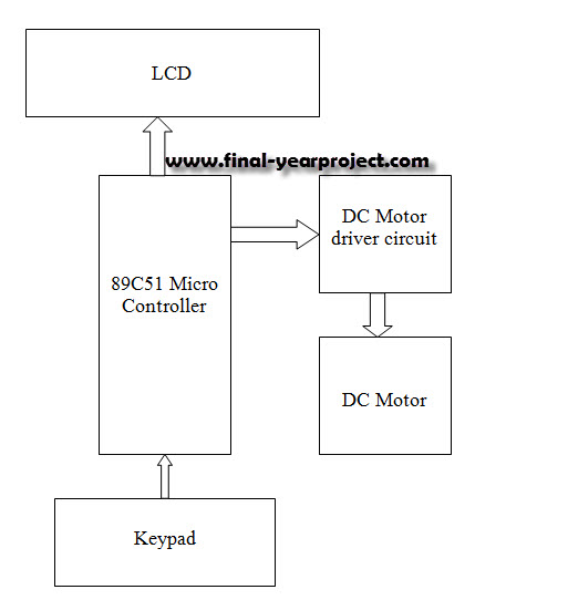
This report details an electronic project focused on the speed control of a DC motor using a microcontroller and PWM (Pulse Width Modulation). The system integrates a microcontroller with an LCD, keypad, and a DC motor driver. The microcontroller...
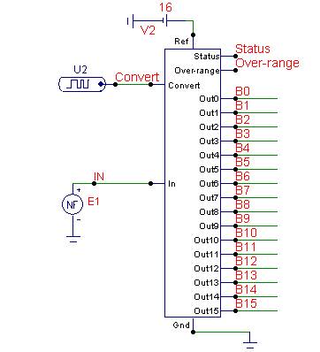
Communication with the MCP3028 ADC chip is achieved through a straightforward serial interface that adheres to the SPI protocol. The PIC16F84 or PIC16F628 does not possess a hardware SPI peripheral. However, a software-implemented SPI protocol can facilitate communication with...
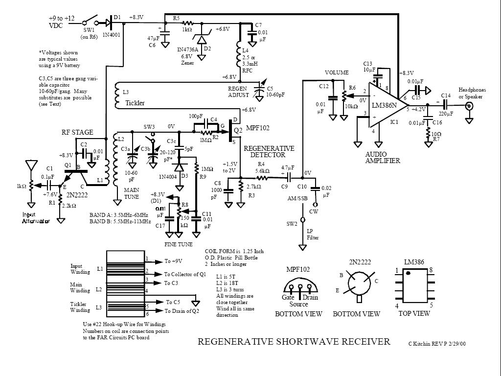
The logical first choice was to start with simple regenerative circuits, utilizing one or two transistors and possibly a basic audio amplifier with a single integrated circuit. A few simple tube radios purchased at flea markets will delay any...