
EM Field Probe with Meter
This electromagnetic field (EMF) tester circuit is designed to accurately detect stray EM fields across a frequency range from 50 Hz to approximately 100 kHz. The circuit employs an operational amplifier (op-amp) as the primary signal processing unit, which amplifies the incoming alternating current (AC) signals generated by nearby electromagnetic sources. The op-amp's gain is influenced by the input capacitance of the probe cable, along with a 150 pF capacitor that rolls off the gain at higher frequencies, ensuring that the circuit remains sensitive to lower frequency signals while preventing distortion at the upper end of its operational range.
The output from the op-amp is an AC voltage that corresponds to the frequency of the detected electromagnetic field. This voltage is then fed into a BC109C transistor, which serves as an additional amplification stage. The transistor enhances the signal strength before it undergoes full-wave rectification. The rectification process converts the AC signal into a direct current (DC) signal, which can be easily measured and displayed.
The rectified output is directed to a meter circuit, which is responsible for providing a visual indication of the detected EM field strength. The design allows for the use of stereo headphones connected to socket SK1, enabling real-time audio monitoring of the detected frequencies. This feature is particularly useful for identifying specific sources of electromagnetic interference, as users can listen to the audio signals generated by the EM fields.
It is important to note that while this circuit is effective at detecting electromagnetic fields, it is not designed to function as a metal detector. However, it can detect metal wiring if it is carrying an AC current, due to the electromagnetic fields generated around the conductors. This capability makes the tester a valuable tool for identifying potential sources of interference in various electronic applications.This tester is designed to locate stray electromagnetic (EM) fields. It will easily detect both audio and RF signals up to frequencies of around 100kHz. Note, however that this circuit is NOT a metal detector, but will detect metal wiring if it conducting ac current. Frequency response is from 50Hz to about 100kHz gain being rolled off by the 150p capacitor, the gain of the op-amp and input capacitance of the probe cable.
Stereo headphones may be used to monitor audio frequencies at the socket, SK1. Meter Circuit: The output signal from the op-amp is an ac voltage at the frequency of the electro-magnetic field. This voltage is further amplified by the BC109C transistor, before being full wave rectified and fed to the meter circuit.
The meter is a sm 🔗 External reference
Related Circuits

This temperature meter utilizes the precision micro power centigrade sensor IC LM35. The output voltage of the IC is linearly proportional to 10 mV per degree centigrade. The LM35 temperature sensor is a versatile and widely used device in electronic...
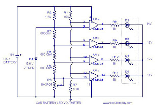
This circuit is a practical device that, when installed in a vehicle, displays the voltage of the car battery using an LED dot display. The meter circuit utilizes four comparators formed from a quad op-amp, specifically the LM324. The...
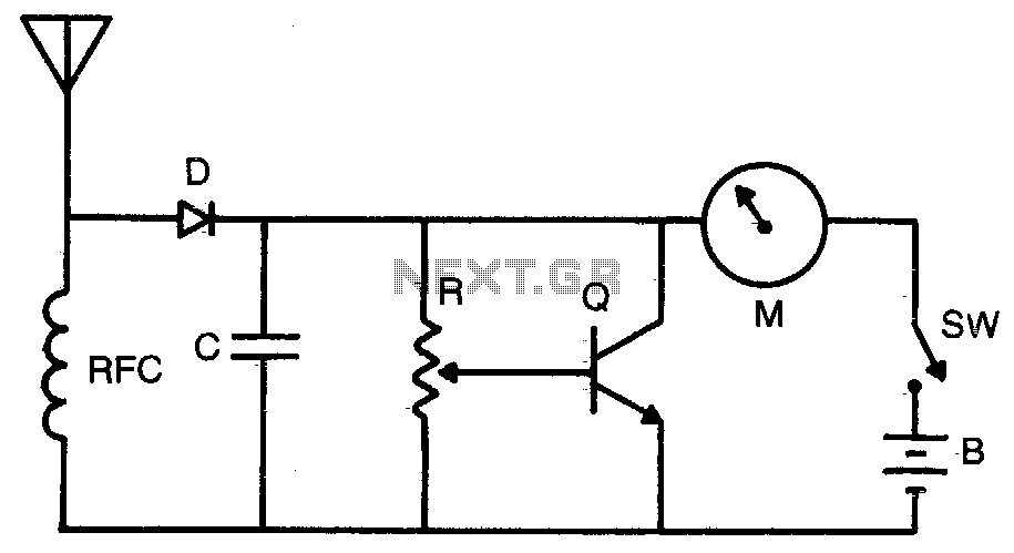
Increased sensitivity provides field strength readings from low-power transmitters. The operating range is 3-30 MHz. To operate, adjust R for Vz to Yz scale reading. RFC = 2 mH choke, C = 1,000 pF, R = 50 K potentiometer,...
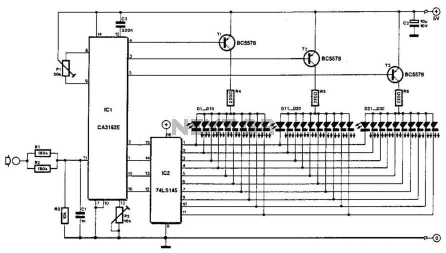
The voltage to be measured is digitized in an analog-to-digital (A/D) converter and then displayed in three decimal digits. The display consists of three groups of 10 LEDs. The meter can only be used for measuring direct voltages. The...
The ADXL362 is an ultra-low power, 3-axis MEMS accelerometer that consumes less than 2 µA at a 100 Hz output data rate and 270 nA when in motion-triggered wake-up mode. Unlike accelerometers that utilize power duty cycling to achieve...
Most analog multimeters are capable of measuring resistance over a wide range of values, but they can be inconvenient to use due to the reverse reading scale, which is also non-linear. Analog multimeters, often referred to as VOMs (Volt-Ohm-Milliammeter), are...