
Linear Resistance Meter
Analog multimeters, often referred to as VOMs (Volt-Ohm-Milliammeter), are versatile instruments used for measuring voltage, current, and resistance. The resistance measurement function is particularly useful for testing components in circuits, verifying connections, and troubleshooting electrical systems. However, the design of the analog multimeter presents some challenges, particularly in the context of resistance measurement.
The reverse reading scale is one of the primary inconveniences associated with analog multimeters. In this configuration, higher resistance values are indicated by lower positions on the scale, which can lead to confusion for users accustomed to direct reading instruments. Additionally, the non-linear nature of the scale means that the spacing between values is not uniform, making it more difficult to estimate precise resistance readings. This non-linearity arises from the way the needle deflection correlates with resistance through the use of a galvanometer, which is inherently more sensitive at lower resistance values.
To enhance the usability of analog multimeters, some designs incorporate features such as a linear scale or a digital readout that can provide a more intuitive understanding of resistance measurements. Additionally, the integration of a switchable range can allow users to select the most appropriate scale for the resistance being measured, thus improving accuracy and reducing the potential for reading errors.
In conclusion, while analog multimeters are effective tools for measuring resistance across a broad spectrum, their usability can be hindered by the reverse reading scale and non-linear characteristics. Understanding these limitations is essential for maximizing the effectiveness of these instruments in practical applications.Most analogue multimeters are capable of measuring resistance over quite a wide range of values, but are rather inconvenient in use due to the reverse reading scale which is also non-linear 🔗 External reference
Related Circuits
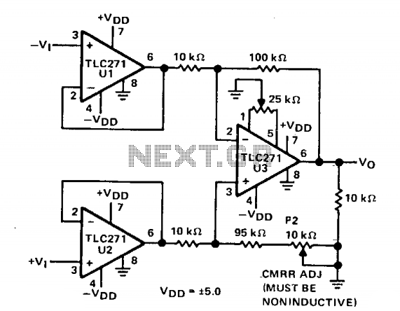
Three operational amplifiers U1, U2, and U3 are configured in a basic instrumentation amplifier arrangement. Operating from ±5 V, pin 8 of each op amp is directly connected to ground, facilitating the desired AC performance for this application (high...

The micro ampere meter presented here functions as a DC millivolt meter. It achieves full-scale deflection with a 0.1V input. The current to be measured flows through a known resistance R, and the voltage drop across this resistance is...
The circuit diagram represents a straightforward circuit-level indication featuring 10 LEDs. It utilizes a series of half-wave rectification controlled by the precision operational amplifier IC2 TL071. The LM3915 integrated circuit is employed to manage the LEDs, functioning as a...
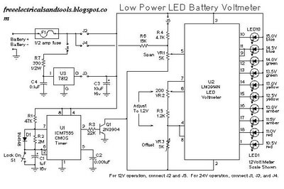
This is a low power voltmeter circuit designed for use with alternative energy systems that operate on 12V and 24V batteries. The voltmeter features an expanded scale that indicates small voltage steps within the 10 to 16 volt range...
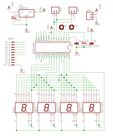
The MAX1496 is an analog-to-digital converter (ADC) that incorporates LED drivers, allowing for the construction of a 3 1/2 digit voltmeter using a minimal number of components. This device features both external and internal voltage reference options, along with...
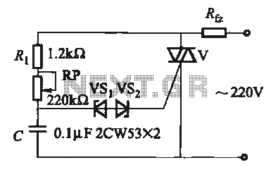
The introduction for a unidirectional thyristor trigger circuit is also applicable to the TRIAC. Several bidirectional circuits are illustrated in Figure 16-28. Figures 16-28 (a) and (b) depict a direct trigger circuit; Figure 16-28 (c) illustrates a dual diode...