
LED Volt Meter Circuit LM324
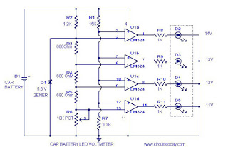
The circuit operates by leveraging the characteristics of the LM324 quad op-amp, which contains four independent, high-gain, frequency-compensated operational amplifiers. Each op-amp is configured as a comparator, comparing the battery voltage against predetermined reference voltages. The use of resistors R3, R4, R5, and R6 establishes these reference levels, which are critical for accurate voltage monitoring.
The voltage divider formed by resistors R1 and R7 scales the battery voltage down to a level that the op-amps can process. This ensures that the non-inverting input receives a voltage that is proportional to the actual battery voltage. When the battery voltage exceeds the reference voltage set at the inverting input, the output of the respective op-amp transitions to a high state, activating the associated LED indicator.
The design allows for a clear visual representation of the battery status; as the voltage increases, different LEDs will light up in succession, providing an immediate indication of the battery's condition. Calibration of the circuit is achieved by adjusting R6, which fine-tunes the reference voltages to match the desired thresholds for battery voltage levels. This adjustment is crucial for ensuring that the circuit accurately reflects the state of the battery, enabling timely maintenance or replacement decisions for the vehicle's power source.
Overall, this circuit is a straightforward yet effective solution for monitoring car battery voltage, enhancing vehicle reliability and maintenance awareness through its visual LED indicators.It`s a very useful circuit which when installed on your car gives the voltage of you car battery in a LED dot display form. The meter circuit is based on four comparators made of quad op amp LM324. The inverting inputs of IC are kept at at reference voltages 5. 6V, 5. 2V, 4. 8V, 4. 4V respectively at pins 2, 6, 9, 13 by resistors, R3, R4, R5, R6. The battery vol tage is directly fed to the non inverting input through the voltage divider arrangement using R1 and R7. When there is variation in the input supply the out put of each op amp goes high accordingly as they are wired as voltage comparators.
The corresponding LED glows. To setup, connect the circuit to battery, adjust R6 so that required voltages are available at the inverting pins( refer description to get the required voltages). 🔗 External reference
Related Circuits
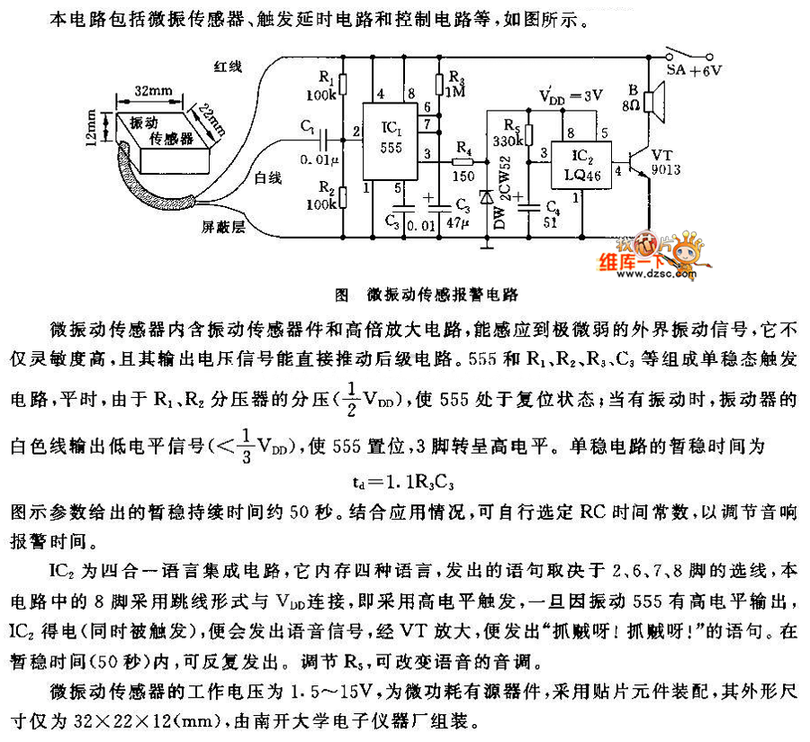
This circuit features a micro vibration sensor, a trigger delay circuit, and a control circuit, as illustrated in the accompanying figure. The micro vibration sensor comprises a vibration sensing device and a high power amplifier circuit, enabling it to...
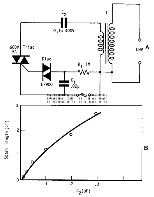
By repetitively charging and discharging a capacitor through the primary winding of an induction coil with high voltage, an ultra-high electromotive force (emf) is induced in the secondary winding. Switching is performed by a triac, which is triggered by...
The keyer dimmer table lamp utilizes two touch buttons to adjust the light intensity. When one button is touched, the light dims from a strong brightness, while the other button increases the brightness from a dim state. The working...
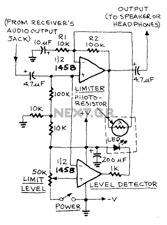
The AUD.LIMITER circuit features a level trim potentiometer that allows for adjustment of the limiting level. When the input signal exceeds the set level of the potentiometer, the output from one half of the operational amplifier, functioning as a...
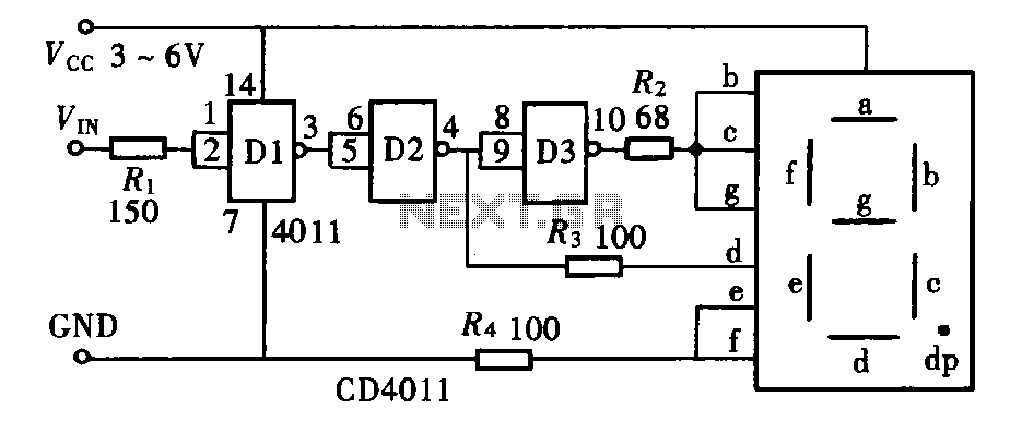
The door circuit logic pen text display can take many forms, utilizing various logic gates such as inverters, NAND gates, NOR gates, and others. A logical pen, exemplified by the NAND gate CD4011, can be used in conjunction with...

The timing circuit utilizes the 556 dual time base circuit, which includes an intermediate access N8281 crossover network. This design does not require a large volume capacitor, allowing for extended time delays. Initially, the first half of the 556...