
Stereo Tv Decoder Circuit

In this circuit, Q1 serves as the audio amplifier, responsible for boosting the audio signal to a suitable level for further processing or output. The audio amplifier typically operates in a linear region to ensure that the fidelity of the audio signal is maintained without distortion. The gain of Q1 can be set by selecting appropriate feedback resistors, allowing for flexibility in audio output levels.
U1 operates at a frequency of 31.5 kHz, which functions as a subcarrier for the audio signal. This frequency is particularly relevant in applications involving frequency modulation (FM) where multiplexing is required. The 38 kHz frequency mentioned in the context of FM multiplexing is often used in stereo broadcasts, where it helps in the separation of left and right audio channels. The 31.5 kHz subcarrier may be used to modulate additional information or channels within the audio signal.
The pilot frequency of 15.734 kHz is crucial for synchronization purposes. In FM broadcasting, a pilot tone is used to indicate the presence of a stereo signal. It allows receivers to lock onto the signal and demodulate it accurately, ensuring that the audio output is clear and free from interference. This frequency is typically generated using a crystal oscillator or a phase-locked loop (PLL) circuit to ensure stability and precision.
Overall, this circuit combines the functionalities of audio amplification and subcarrier generation to facilitate high-quality audio transmission, particularly in FM multiplexing applications. Proper design considerations, such as filtering and impedance matching, should be taken into account to optimize performance and minimize signal degradation. Ql is an audio amplifier and Ul is used as a 31.5-kHz subcarrier, which is similar to 38-kHz FM MPX. Pilot frequency is 15.734 kHz. 🔗 External reference
Related Circuits
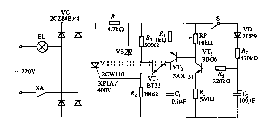
A fade-in fade-out light switch enables gradual adjustments in lamp brightness, allowing the light to turn on and off smoothly. When the switch SA is closed, the lamp brightness increases from dim to bright. Conversely, when the switch SA...
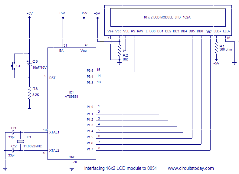
Interfacing a 16x2 alphanumeric LCD module with the AT89S51 microcontroller. The circuit diagram, theory, and program are included. JHD162 LCD module pinout and commands are provided. The integration of a 16x2 alphanumeric LCD module with the AT89S51 microcontroller involves several...
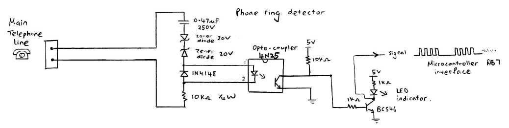
This circuit detects the dial tone from a telephone line and decodes the keypad pressed on the remote telephone. The dial tone heard when picking up the phone is referred to as Dual Tone Multi-Frequency (DTMF). This name originates...
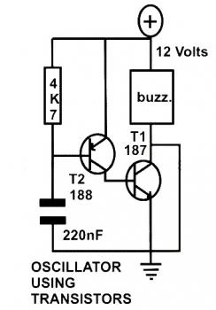
This schematic diagram represents a basic oscillator circuit utilizing two transistors. When the transistors and several passive components are connected as illustrated, the circuit begins to oscillate. The oscillation frequency can be modified by altering the values of either...
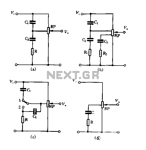
Figure 1.88 illustrates the loudness control circuit utilizing multiple taps on a potentiometer. In Figure (A), the connection is made between the tap and the potentiometer's input, along with the ground. An RC compensation network is employed, where the...
555 timer circuits LM555 - Astable Oscillator Calculator, Capacitor Calculator, Basic Circuits for the LM555 Timer, Triggering and Timing Helpers for Monostable Timers, Controlling Circuits for LM555 Timers, Advanced Circuits for the LM555 Timer, LM556 Timers with Complementary or...