
FM remote Encoder/Decoder
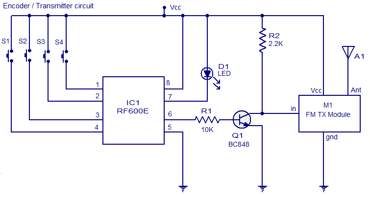
The FM remote encoder/decoder circuit is a sophisticated system designed to facilitate wireless communication with a focus on security applications. The RF600E IC, functioning as the encoder, converts the input signals from the push button switches into a coded output. Each switch corresponds to a specific function, enabling control over various devices remotely. The buffering of the encoded signal through transistor Q1 ensures that the signal strength is adequate for transmission, minimizing the risk of data loss.
The FM transmitter module (M1) plays a crucial role in the circuit, as it modulates the encoded signal onto a carrier frequency suitable for FM transmission. This allows for reliable communication over distances, making it ideal for applications such as remote control systems and alarm systems. The choice of a general-purpose FM transmitter module enhances the flexibility of the design, enabling easy sourcing and integration.
On the receiving end, the RF600D IC decodes the received FM signal. The digital data output pins provide a direct interface to control other electronic components or systems based on the received commands. The ability to switch between latching and momentary output functions adds versatility to the system, catering to different operational requirements.
The learning feature of the system, facilitated by switch S5, allows for easy integration of multiple transmitters. This capability is particularly useful in applications requiring multiple remote controls, such as home automation or security systems. The visual feedback from the status LED D2 during the learning process ensures that users can easily understand the system's state, simplifying the setup procedure.
Overall, this FM remote encoder/decoder circuit represents a robust solution for wireless control applications, leveraging the capabilities of RF600E and RF600D ICs to provide a secure and efficient communication method.Here is the circuit diagram of an FM remote encoder/decoder using the ICs RF600E and RF600D. These devices are designed to provide a high level of security and operates from anything between 2 to 6. 6V DC. Various electronic circuits like remote control systems, remote alarm systems, anti theft alarms etc can be implemented using the RF600E/RF600D
pair. The remote systems given here uses FM for the transmission. IC1 RF600E and its associated components form the encoder circuit. Pins 1 to 4 forms the switch inputs of IC1. When each push button switch is pressed a corresponding code will be generated at the pin 6 which is the data output pin. The encoded signal available at pin 6 is buffered using the transistor Q1 and the fed to the input of a general purpose FM transmitter module (M1).
Such FM transmitter modules are very common in the market now. The decoder system comprises of the IC2 RF600D and its associated components. Pins 17, 18, 1 and 2 are the digital data output pins of RF600D corresponding to the input switches S1 to S4 of the encoder/transmitter circuits. The digital data output pins 17, 18, 1 and 2 are asserted low when the relevant inputs S1 to S4 on the IC2 RF600E are asserted.
M2 is a general purpose FM receiver module which receives the transmitted code and feds it to the data input (pin 9) of the IC2. Switch S1 can be used to select between latching and momentary digital output function. In latching mode digital output pins (OP1 to OP4) are only asserted for the corresponding transmit signal.
In latching mode the output state is changed on each corresponding transmit signal. The learn switch S5 is used to enter the decoder IC in to the learn mode . Learn operation using push button switch S5 is as follows. 1) Press and release the push button switch S5. 2) The status LED D2 will glow when S5 is pressed and will remain ON when S5 is released. 3) Operate the encoder/transmitter once. 4) The status LED D2 will become OFF. 5) Operate the encoder/transmitter again. 6) The status LED will start flashing. 7) When the flashing of status LED stops, the encoder will be successfully taught to the decoder and the transmitter/encoder will now operate the receiver/decoder system. Up to seven encoder/transmitters can be learnt to each RF600D. Pin 3 of IC2 is the transmitter low battery indicator output and pin 11 is the serial data output. 🔗 External reference
Related Circuits
A few designs for remote control switches, using VG40T and VG40R remote control pair, are shown here. The miniature transmitter module shown in Fig. 1, which just measures 34 mm x 29 mm x 10 mm, can be used...
This transmitter emits an FM signal within the 88 to 108 MHz frequency range, featuring a tone of 19 kHz. It is designed to activate the FM MPX pilot carrier indicator, enabling interfacing with external devices. L4 is intended...
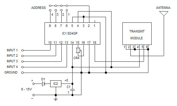
The Glolab ED4GP microprocessor-based Encoder/Decoder is designed for use with wireless modules, infrared remote controls, and other devices that operate with serial input and output data. It can function as either an encoder or a decoder by connecting pin...

The board can now be tested. Set the DIP switch to Switch1 ON, Switch2 OFF (15-second delay), Switch3 ON, and Switch4 OFF (4 rings to activate half for switching ON). To switch ON relay 1 (connected to RB0 of...
The DTMF codec stands for dual-tone multi-frequency codec. The multiple-channel infrared remote control switch circuit that incorporates the DTMF is depicted in the figure. It consists of an infrared remote control signal emitter, an infrared receiving signal amplifier, a...
This small circuit is designed to verify the basic functionality of an infrared remote control unit. The circuit utilizes a straightforward approach by connecting a piezo buzzer directly to an IR receiver integrated circuit (IC). This configuration is as...