
Thermocouple cold junction compensation RTD has XTR101 Input Circuit
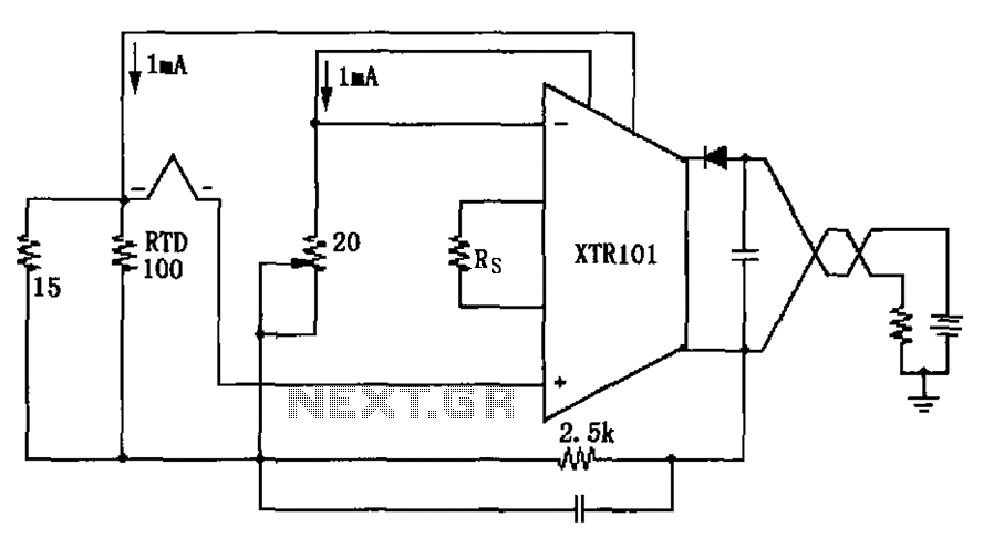
The schematic features a type J RTD, which operates on the principle that the resistance of the sensor varies with temperature changes. Specifically, a type J RTD typically has a resistance of 100 ohms at 0°C, with a temperature coefficient of approximately 0.00385 ohms per degree Celsius. This characteristic allows for accurate temperature measurements across a specified range.
The circuit includes an operational amplifier configured as a differential amplifier to process the small voltage signals generated by the RTD. The output from the RTD is fed into the non-inverting and inverting inputs of the op-amp. This configuration enhances the signal-to-noise ratio, ensuring precise readings.
In addition, a 20-ohm potentiometer is integrated into the circuit for zero-point calibration. This adjustment allows for fine-tuning the output to zero at a known reference temperature, ensuring accuracy in temperature readings. The potentiometer is connected in series with a resistor, allowing for smooth adjustments to the baseline output voltage.
The output from the op-amp is then typically connected to an analog-to-digital converter (ADC) for digital processing or to a microcontroller for further data handling and display. This setup enables the monitoring of temperature in real-time, making it suitable for applications in industrial processes, HVAC systems, or laboratory environments.
Overall, the described circuit effectively combines the properties of the type J RTD with appropriate signal conditioning and calibration techniques, resulting in a reliable temperature measurement system. As shown, the circuit uses type J RTD, its resistance value corresponds to the temperature of the RTD can check a form provided by the manufacturer, with 20 zero adjustment pot entiometer zero point calibration.
Related Circuits
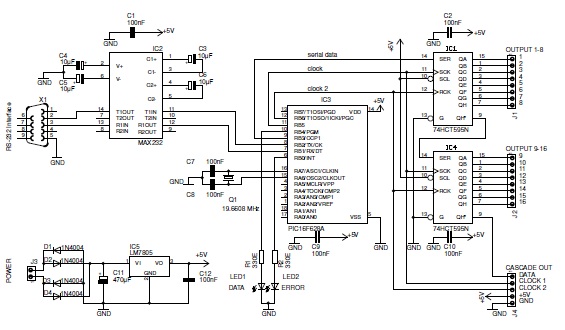
This basic PIC-based RS-232 serial interface can control up to 120 digital TTL outputs. The described circuit utilizes a PIC microcontroller to facilitate communication via the RS-232 protocol, which is a standard for serial communication. The interface primarily serves to...
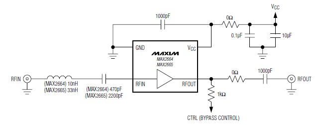
A simple, low-cost, and ultra-compact VHF/UHF low-noise amplifier circuit can be designed using the MAX2664 and MAX2665 ultra-compact LNAs for VHF/UHF applications. These devices incorporate a broadband LNA with an integrated bypass switch. The MAX2664 covers the UHF frequency...
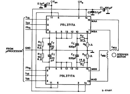
The PBL3717A stepper motor driver is a monolithic integrated circuit that controls and drives one phase of a bipolar stepper motor utilizing chopper control for phase current regulation. Current levels can be selected in three increments using two logic...
The electronic fishing shrimp machine circuit consists of an astable oscillator, an inverter circuit, and a high-voltage output circuit, as depicted in Figure 20. The astable oscillator circuit includes a time-base integrated circuit (IC), resistors R3 and R4, a...
The figure illustrates a schematic circuit of a UV sensor. When voltage is applied between the cathode and anode, and UV radiation passes through the quartz glass tube on the cathode's optical surface, the cathode material, which is coated...
This is a simple circuit diagram for a 150W power amplifier. The circuit can be constructed without a printed circuit board (PCB). The power output ranges from 100W to 150W, depending on the power supply and the Darlington transistors...
Warning: include(partials/cookie-banner.php): Failed to open stream: Permission denied in /var/www/html/nextgr/view-circuit.php on line 713
Warning: include(): Failed opening 'partials/cookie-banner.php' for inclusion (include_path='.:/usr/share/php') in /var/www/html/nextgr/view-circuit.php on line 713