
8MHz AM radio transmitter circuit
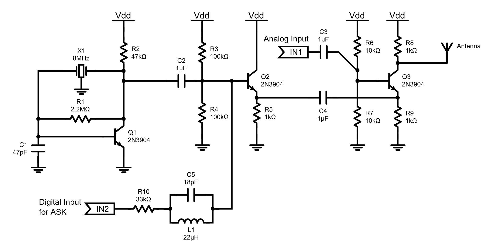
The circuit is divided into three main components: the oscillator, the buffer, and the mixer. It operates on a power supply voltage of 3.3V. The oscillator generates the 8MHz carrier signal and is implemented as a minimalist single-transistor (Q1) Pierce oscillator, based on the design outlined in National Semiconductor Application Note 400 (AN400 – A study of the crystal oscillator for CMOS-COPS, Fig 6). The resonating element is an 8MHz ceramic resonator (X1) with integrated capacitances, supplemented by an additional capacitor (C1) to ensure proper oscillation.
The buffer serves to isolate the oscillator from the loading effects of the mixer, utilizing a standard emitter follower configuration with transistor Q2. Direct connection of the oscillator to the mixer would compromise its functionality, which is why the buffer is a critical component of the design. The possibility of removing the buffer by increasing the input impedance of the mixer was not explored.
This AM radio transmitter circuit exemplifies fundamental principles of RF design and serves as a practical tool for both educational and experimental purposes. The choice of components, such as the ceramic resonator and transistors, reflects a balance between performance and accessibility, making it suitable for both novice and experienced electronics enthusiasts. The circuit's simplicity allows for easy troubleshooting and modifications, which can further enhance the learning experience for students and hobbyists alike. The design can also be expanded or adapted for various applications, including signal processing and communication experiments.This is an 8MHz amplitude modulated (AM) radio transmitter, which I built mainly for work, and also as an exercise in electronics (it is the first RF transmitter I’ve ever built). We wanted to have a simple radio transceiver design at our disposal for some possible projects in the future that might require a primitive means of short range wireless communications.
Also considered was the possibility of getting kids to build this as part of the courses we teach in secondary schools. The buffered carrier signal goes to the mixer circuit, where its amplitude gets modulated by the analog signal input from IN1.
This is just a common-emitter ‘amplifier’ with the transistor (Q3) biased close to / in the saturation region which is necessary for the whole thing to work as a mixer. The output of the mixer connects directly to the antenna, which is nothing more than a rather long (>30cm) length of wire.
The circuit consists of 3 parts: oscillator, buffer, and mixer. It runs on a power supply voltage of 3.3V. The oscillator produces the 8MHz carrier signal. It is a minimalist single-transistor (Q1) Pierce oscillator, and the design comes from National Semiconductor Application Note 400 (AN400 – A study of the crystal oscillator for CMOS-COPS, Fig 6). The resonating element is an 8MHz ceramic resonator (X1) with built-in capacitances (we have quite a few lying around in the office).
An additional capacitance C1 is necessary to get the circuit to oscillate properly. The buffer isolates the oscillator from loading by the mixer. It is a standard emitter follower circuit using Q2. The oscillator will not work properly if connected directly to the mixer. I did not explore the possibility of eliminating the buffer by increasing the input impedance of the mixer. 🔗 External reference
Related Circuits
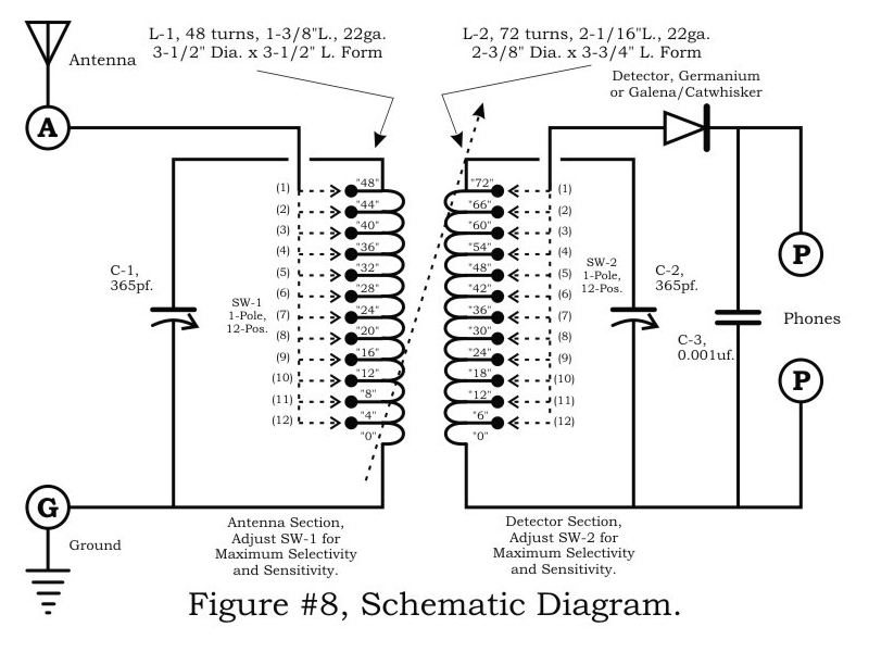
A two-circuit tuner, similar to a loose coupler, is an effective method for achieving selectivity without compromising sensitivity. The circuit introduces the signal to the primary antenna section via the SW-1 arrangement, allowing the antenna to be matched to...
In this project, you will make a simple low-power broadcast-type circuit, using a crystal oscillator integrated circuit and a collector modulated AM oscillator. You can connect the circuit to an amplified microphone (no amplified microphone has a too low...
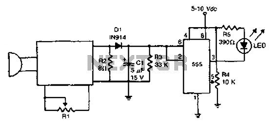
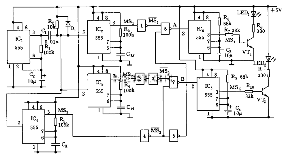
The acoustic detector consists of a Schmitt trigger IC555 connected to various components. When the input exceeds a certain voltage, the output will change state from high to low. R4 is used to set the threshold voltage. The acoustic detector...
The capacitor filter operates by measuring the capacitance, which is proportional to the pulse width. This measurement is compared to a nominal capacitance to determine qualification. The circuit, as illustrated in the accompanying figure, includes IC1 along with resistors...
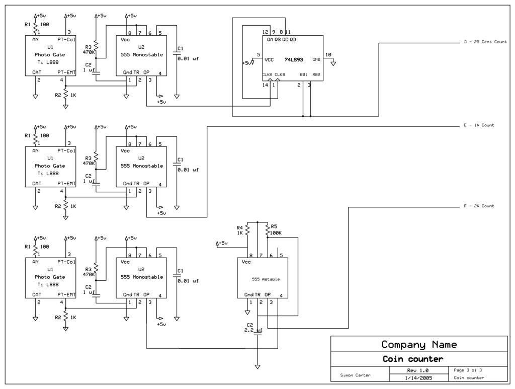
The next counter section operates similarly but is designed to count four quarters, single $1 coins (loonies), and single $2 coins (toonies). The circuit for the toonies is configured. The circuit for the counter section includes a digital counting mechanism...
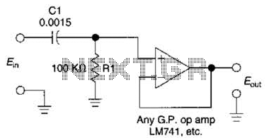
This simple 1 kHz filter utilizes a voltage follower and an RC section as its filtering element. For other frequencies, the -3 dB point is given by the formula 1/(6.28 Rl Cv), and the response decreases at a rate...
Warning: include(partials/cookie-banner.php): Failed to open stream: Permission denied in /var/www/html/nextgr/view-circuit.php on line 713
Warning: include(): Failed opening 'partials/cookie-banner.php' for inclusion (include_path='.:/usr/share/php') in /var/www/html/nextgr/view-circuit.php on line 713