
Energy-Saving Switch Schematic

The circuit operates on a simple yet effective principle, utilizing two relays to manage the illumination levels of the connected lamps. The initial gentle illumination is handled by LA1, which is powered through RE1's normally closed contact. When the switch is toggled off and back on within one second, RE2 engages, allowing for a temporary increase in brightness through LA2. This mechanism leverages the rapid response of RE2 to create a momentary surge in current that energizes LA2, providing a brighter light.
The design incorporates a time delay feature that is essential for preventing accidental toggling back to LA1. The delay is achieved through the RC time constant formed by R1 and C1, which controls the charging and discharging behavior of the capacitor. This ensures that RE1 remains inactive during brief interruptions, allowing the circuit to stabilize before returning to its original state.
Safety is paramount in this circuit design. The use of a well-insulated ABS plastic enclosure safeguards against accidental contact with high-voltage components, thereby minimizing the risk of electric shock. The printed circuit board layout should be designed with careful consideration of component placement to reduce the risk of arcing or short circuits, particularly in areas where high voltage is present.
When implementing this circuit, it is advisable to follow local electrical codes and regulations to ensure compliance and safety standards. Proper labeling of the enclosure and clear instructions for users can further enhance safety and usability.Normal operation of the light switch gives gentle illumination (LA1). For more light, simply turn the switch off and then immediately (within 1 s) on again. The circuit returns to the gentle light set-ting when switched off for more than 3 s. There is no need to replace the light switch with a dual version: simply insert this circuit between switch and lamp. Almost immediately after switch-on, fast-acting miniature relay RE2 pulls in, since it is connected directly after the bridge rectifier. Its nor-mallyclosed contact then isolates RE1 from the supply, and thus current flows to LA1 via RE1`s normally-closed con-tact.
RE1 does not have time to pull in as it is a power relay and thus relatively slow. Its response is also slowed down by the time constant of R1 and C1. If the current through the light switch is briefly interrupted, RE2 drops out immediately. There is enough energy stored in C1 to activate RE1, which then holds itself pulled in via a second, normally-open, contact. If current starts to flow again through the light switch within 1s, LA2 will light. To switch LA1 back on it is necessary to turn the light switch off for more than 3 s, so that C1 can discharge via R2 and RE1.
The printed circuit board can be built into a well insulating plastic enclosure or be incorporated into a light fitting if there is sufficient space. the printed circuit board is connected directly to the mains-powered lighting circuit. Every precaution must be taken to prevent touching any component or tracks, which carry dangerous voltages.
The circuit must be built into a well insulated ABS plastic enclosure. 🔗 External reference
Related Circuits
Built around an LM380, this amplifier includes tone controls and electronic "soft switching". The soft switching circuitry ensures power is built up gradually eliminating the dc thump. The soft switching is enabled by a BD131 transistor wired as a...
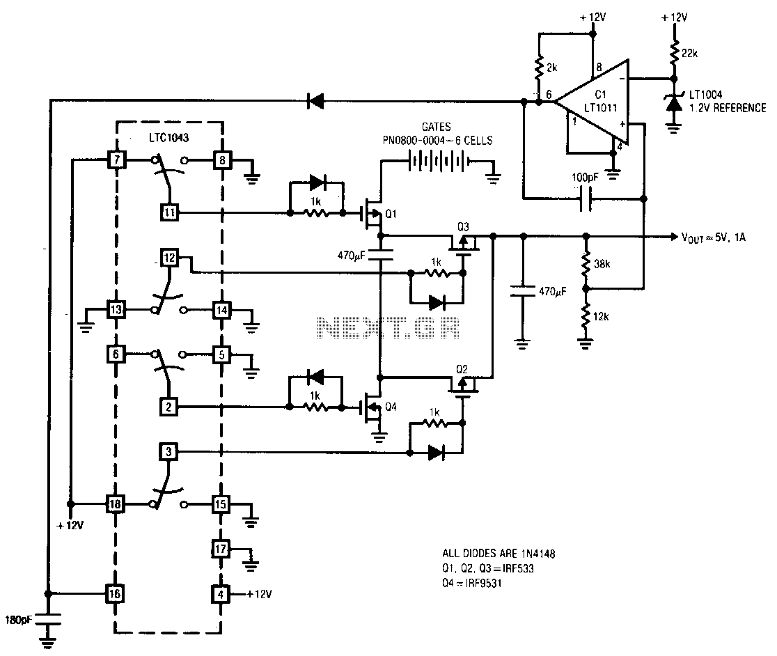
The LTC10432 switched-capacitor building block provides non-overlapping complementary drive to the Q1 to Q4 power MOSFETs. The MOSFETs are arranged such that C1 and C2 are alternately placed in series and parallel configurations. During the series phase, the +12...
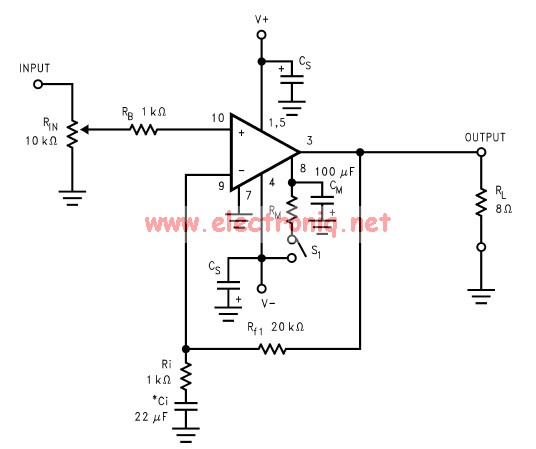
The LM3886 amplifier electronic circuit project is designed to deliver 68W of continuous average power into a 4-ohm load and 38W into an 8-ohm load with a total harmonic distortion plus noise (THD+N) of 0.1% across the frequency range...
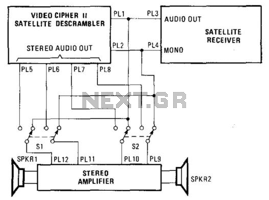
Some channels provide a separate audio mode (SAP) in an alternate language, typically transmitted at 6.8 MHz, which is the frequency designated for unscrambled channels. In scrambled channels, audio is transmitted alongside the video signal, allowing the descrambler to...
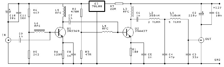
A high-efficiency, simple two-transistor VHF amplifier electronic circuit project can be developed using the provided circuit diagram. This VHF amplifier circuit achieves a significant efficiency with a gain of approximately 16 dB and does not require any tuning or...
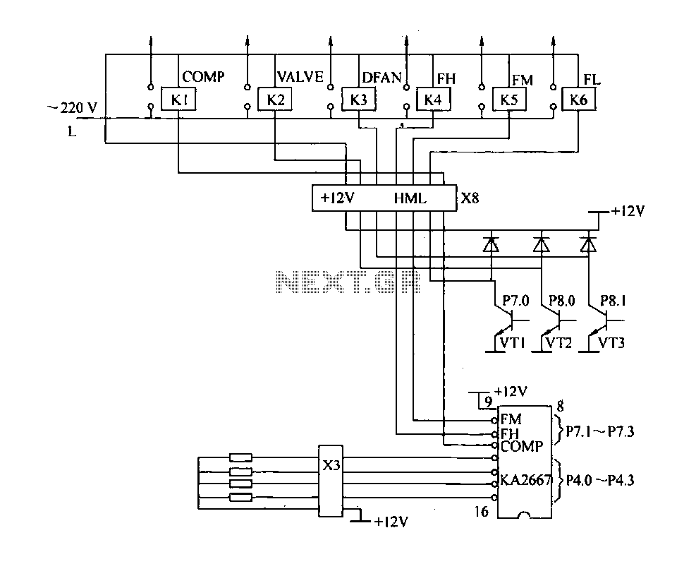
The driving circuit depicted in Figure 18-12 consists of a connection between the driving portion, the microcontroller, and the air conditioning operation components of the bridge. The microcontroller's digital signal levels from ports P4.0 to P4.3 (approximately 12 feet)...