
Enhanced 4 Digit Alarm Keypad
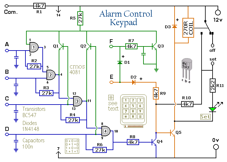
The described keypad is a standard 12-key configuration, typically used in security systems and user interfaces for alarm activation and deactivation. The keypad features a common terminal, which serves as a reference point for the electrical connections, and individual terminals for each of the twelve keys. This configuration allows for straightforward wiring and reliable operation.
In this setup, there are 13 terminals in total: one common terminal and one for each of the 12 keys. The requirement for a separate connection for each key ensures that each key press can be individually detected by the connected microcontroller or alarm system. This is essential for applications where multiple keys might be used for different functions, such as arming or disarming an alarm system.
The alarm system is activated by pressing a designated key, which is wired to terminal E. This key serves as the primary activation switch for the alarm. The choice of this key can be tailored to user preference, allowing for ease of access and usage.
To deactivate the alarm, four additional keys are designated, connected to terminals A, B, C, and D. These keys can be selected based on user convenience and can include alphanumeric characters or symbols, expanding the potential for unique codes. The ability to include non-numeric symbols significantly increases the complexity of the security code, providing over 10,000 possible combinations when using a 12-key pad. This diversity in codes enhances the security of the system, making unauthorized access more difficult.
When designing the wiring layout, it is crucial to ensure that the common terminal is properly connected to the ground or power supply, depending on the specific requirements of the alarm system. Each of the individual key terminals must be connected to the input pins of the microcontroller or alarm circuit, which will monitor the state of each key press.
In summary, the described keypad configuration is effective for creating a secure and user-friendly alarm system, leveraging a 12-key layout with distinct connections for each key to maximize functionality and security.The Keypad must be the kind with a common terminal and a separate connection for each key. On a 12-key pad, look for 13 terminals. The matrix type with 7 terminals will NOT do. The Alarm is set by pressing a single key. Choose the key you want to use and wire it to `E`. Choose the four keys you want to use to switch the alarm off, and connect them to `A B C & D`. Your code can include the non-numeric symbols. With a 12-key pad, over 10 000 different codes are available. 🔗 External reference
Related Circuits

The B8422 Nixie tubes are intended for use in an alarm clock on a bedside table. The collection of homemade clocks in the house has expanded, with the bedroom remaining unaffected by this clock-making enthusiasm. The B8422 Nixie tubes,...

This simple alarm timer circuit is constructed using a 4060 IC, which features an integrated oscillator known for its good stability and relatively wide frequency range. The 4060 integrated circuit (IC) serves as the core component of this alarm timer...

A simple alarm circuit with a diagram and schematic that generates a multi-tone sound. This alarm circuit is suitable for use in burglar alarms and sirens and is designed using dual op-amps MC1458 and LM380. The described alarm circuit utilizes...
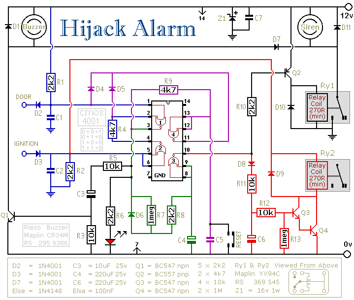
The first circuit is designed for situations where a hijacker forces the driver from the vehicle. If a door is opened while the ignition is switched on, the circuit will activate. After a few minutes delay, when the thief...
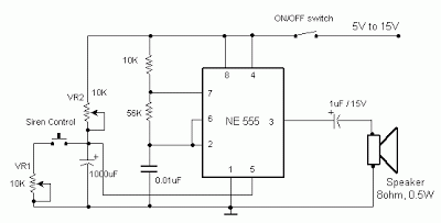
The frequency is controlled by pin 5 of the integrated circuit (IC). When the power supply is activated, the capacitor charges gradually, which alters the voltage at pin 5 of the IC, causing the frequency to increase incrementally. Once...
The PGA202 is a digitally controlled programmable gain amplifier with gain settings of G = 1, 10, 100, and 1000. The PGA203 offers gain settings of G = 1, 2, 4, and 8. Both amplifiers are compatible with CMOS...