
Hijack Alarm
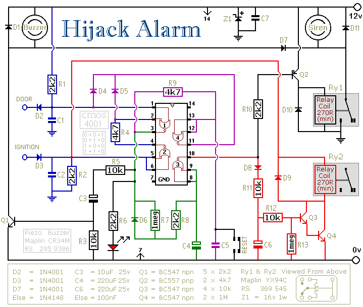
The circuit operates by monitoring the state of the vehicle's doors and ignition system. When the ignition is on and a door is opened, the circuit triggers an alarm condition. The initial alert is provided by the buzzer, which sounds for a brief duration, prompting the driver to reset the system. The components involved in the alarm include a timer circuit, which is configured using resistors R7 and R13 alongside capacitors C4 and C6 to establish the timing for the delay before the siren and buzzer activate. The reset mechanism is crucial for the functionality of the system, allowing the driver to deactivate the alarm under safe conditions.
A relay, suitable for automotive applications, is essential for controlling the engine cut-off mechanism. The relay's contacts are used to interrupt the ignition system, ensuring that the engine ceases operation when the alarm state is reached. The design also incorporates a diode to protect the control circuitry from voltage spikes generated by the relay coil during deactivation.
In terms of installation, careful attention must be given to the placement of components to avoid exposure to moisture and ensure reliable operation. The use of a fuse is critical to safeguard against potential short circuits, and the choice of materials should prioritize durability and resistance to environmental conditions. Overall, this circuit provides a robust solution for enhancing vehicle security, minimizing the risk of unauthorized use while considering safety and legal implications.The first circuit was designed for the situation where a hijacker forces the driver from the vehicle. If a door is opened while the ignition is switched on - the circuit will trip. After a few minutes delay - when the thief is at a safe distance - the alarm will sound and the engine will fail.
Before fitting this or any other engine cut-out to you r vehicle - carefully consider both the safety implications of its possible failure - and the legal consequences of installing a device that could cause an accident. If you decide to proceed - you will need to use the highest standards of materials and workmanship. You`re going to trip this alarm unintentionally. When you do - the LED will light and the Buzzer will give a short beep. The length of the beep is determined by C3. Its purpose is to alert you to the need to push the reset button. When you push the button - the LED will switch-off. Its purpose is to reassure you that the alarm has in fact reset. If the reset button is not pressed then - about 3 minutes later - both the Siren and the Buzzer will sound continuously.
The length of the delay is set by R7 & C4. For extra effect - fit a second siren inside the vehicle. With enough noise going on - you may feel that it`s unnecessary to fit the engine cut-out. In which case - you can leave out D8, D9, R11, R12, R13, C6, Q3, Q4 & Ry2. Even if you missed the early warning provided by the Buzzer - there is still time to reset the alarm before Ry2 de-energizes - and the engine fails. This additional delay - currently about 1 minute - is set by C6 and R13. To reset the circuit you must - EITHER turn off the ignition - OR close all of the doors - before you press the reset button.
While BOTH the ignition is on - AND a door remains open - the circuit will NOT reset. The reset button carries virtually no current - so any small normally-open switch will do. Eric Vandel from Canada suggests using a reed-switch hidden behind (say) the dash - and operated by a magnet. I think this is an excellent idea. As Eric said in his email: - ". that should keep any thief guessing for a while. " The Flow Chart is another of Eric`s suggestions. It will help you to visualize how the alarm is operated. It also explains the sequence of events that lead to siren activation - and subsequent engine failure.
How you bring your vehicle to a standstill is up to you. It should happen when Ry2 de-energizes. The contacts of Ry2 are too small to do the job themselves. So use them to switch the coil of a larger relay. Remember that the relay must be suitable for the current it`s required to carry. Choose one specifically designed for automobiles - it will be protected against the elements - and will give the best long-term reliability. You don`t want it to let you down on a cold wet night - or worse still - in fast moving traffic! Remember also that you must fit a 1N4001 diode across YOUR relay`s coil - to prevent damage to the Cmos IC.
YOUR relay should drop-out when Ry2 de-energizes. Wire YOUR relay so that when it drops-out the engine will stop. Because turning-off the ignition will cause both Ry2 and YOUR relay to de-energize - the standby current will be low - and the engine will be disabled while the vehicle is parked. The circuit board must be protected from the elements. Dampness or condensation will cause malfunction. Fit a 1-amp in-line fuse AS CLOSE AS POSSIBLE to your power source. This is VERY IMPORTANT. The fuse is there to protect the wiring - not the components on the circuit board. Please note that I am UNABLE to help any further with either the choice of a suitable relay - or with advice on installation.
Both the Siren and the Buzzer will go on sounding until the alarm is reset. The circuit is designed to use an electronic Siren drawing up to about 500mA. It`s not usually a good idea to use the vehicle`s own Horn because it can be easily located and disconnected. However, if you choose to 🔗 External reference
Related Circuits
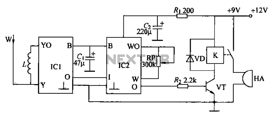
A circuit for an inductive burglar alarm is derived from a radio scanning detection circuit, which includes a signal processing circuit and an alarm circuit. The radar detection circuit module consists of components such as microwave emission, low-pass filtering,...
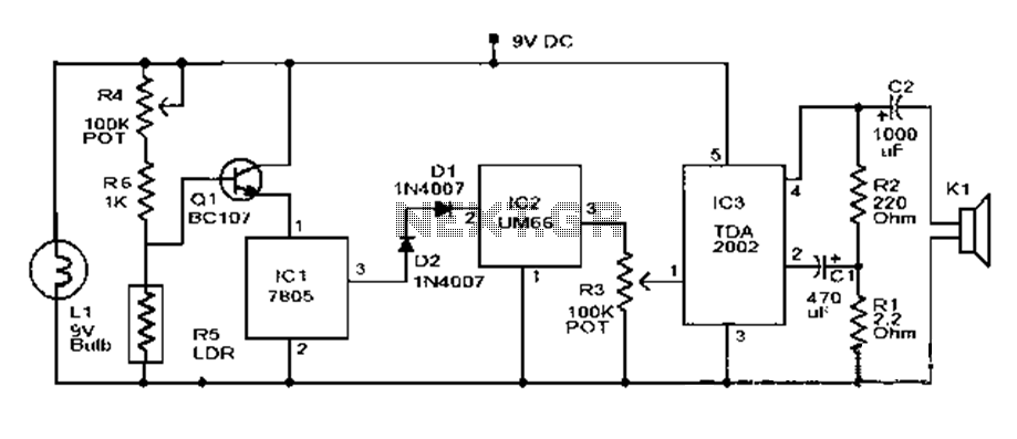
This document outlines a basic fire alarm circuit utilizing an LDR (Light Dependent Resistor) for fire detection. The circuit is designed to generate an audible alarm in response to smoke, which affects the LDR's resistance. In the absence of...

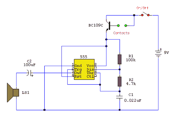
This circuit features an astable oscillator constructed around a 555 timer, generating an alarm tone of 1.8 kHz, which directly drives a speaker. It serves as a fundamental alarm circuit that can be utilized in various projects. Although the...
Under dry conditions, the transistor will not have any bias current and will be completely off. However, when the probes become wet, the transistor will conduct, triggering the alarm. An On/Off switch is included, and it is important to...
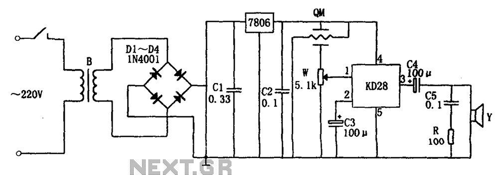
The system includes a gas-sensitive sensor element QM (type QM-N5), a buck rectifier, and regulator circuits, integrated circuits KD28, a speaker Y, and other components. The buck regulator circuit features a transformer rectifier and a bridge rectifier comprising diodes...
This is a security alarm. If someone disconnects the wire loop, the speaker will generate a sound. A circuit has been used for this system. When a burglar enters the property, it provides an early warning. When setting up...
Warning: include(partials/cookie-banner.php): Failed to open stream: Permission denied in /var/www/html/nextgr/view-circuit.php on line 713
Warning: include(): Failed opening 'partials/cookie-banner.php' for inclusion (include_path='.:/usr/share/php') in /var/www/html/nextgr/view-circuit.php on line 713