
Talking Nixie Alarm Clock

The B8422 Nixie tubes serve as the visual centerpiece of the alarm clock design, enhancing both functionality and aesthetic appeal. Their semi-rectangular shape allows for efficient digit arrangement, which is ideal for applications requiring compact displays. The design incorporates a flyback converter to generate the high voltages necessary for the operation of the Nixie tubes, ensuring that the circuit can deliver the required performance while maintaining compactness.
The use of a 16F84 PIC processor facilitates the control of the clock's functions, including timekeeping and the operation of the Nixie tubes. However, due to its limited I/O capabilities, the design strategically employs shift registers to manage the output to the 74141 Nixie tube drivers. This configuration allows for a simplified wiring approach while ensuring that all necessary outputs are accounted for.
The implementation of a talking feature adds a personal touch to the alarm clock. By recording messages from family members, the project not only serves a practical purpose but also fosters emotional connections through the integration of audio clips. The use of EPROM for audio storage provides flexibility in updating or changing wake-up messages as desired.
To further extend the life of the Nixie tubes, the design incorporates a feature that turns off the tube displays during daylight hours, effectively reducing wear and tear. This consideration for longevity is crucial in ensuring that the Nixie tubes remain functional for extended periods, aligning with the overall goal of creating a reliable and aesthetically pleasing alarm clock.
In summary, the design of the B8422 Nixie tube alarm clock integrates advanced electronic components and thoughtful design choices to create a unique and personalized timekeeping device. The combination of visual appeal, emotional resonance through audio messages, and practical considerations for component longevity culminates in a sophisticated project that showcases the capabilities of modern electronics.The B8422 Nixie tubes were destined to end up in an alarm clock on my bedside cupboard. My house is slowly filling up with homemade clocks, only our bedroom has so far been saved from the "collateral damage" of my clock making mania. A set of romantically glowing nixie tubes will make a big improvement compared to the ordinary twenty year old
LED alarm clock I use now. The B8422 is a lovely "top-view" Nixie tube with a very characteristic semi-rectangular (or semi-round) shape (Fig. 3). This peculiar shape makes it possible to make a row of closely spaced digits e. g. for a calculator read-out, which would have been impossible with a perfectly round top-view type like e.
g. the B5031 or ZM1020 For years I have been playing around with the idea of making a talking clock. It seemed to me to be a nice idea to capture the voice of somebody who is special to me, so that I could hear the voice of that person telling the time, even when that person is not there (anymore). EPROMs now have such a large memory capacity that they can easily store a minute or so of audio with quite a reasonable quality.
Instead of telling the time I decided to record and store a number of wake-up messages spoken by my sons (Geert 9 and Daan 6). As I am very fond on them, I though that I will wake up a lot more relaxed hearing their voices instead of an angry buzzer.
For the case I want to use the other half of the Plexiglas tube I had left over from the "NIXIE I" clock. The somewhat limited space available in this tube more or less dictated the, at first sight, slightly strange distribution of the clock circuit over the three PCBs.
At the writing of this page the final case of this clock was not yet finished. As always I find it the most difficult part of building a clock. When it is ready I will add a picture of the final clock to this page. I will first describe the circuit of the clock itself (Nixies, drivers, processor, flyback converter and timebase). Next the realization of these circuits will be discussed, followed by the speech "generator" which is a kind of stand alone circuit.
The speech, which is stored in an EPROM, is generated from an ordinary wav file. How this is done will be discussed in detail. Finally I will summarize the control of the clock and outline the software. As always all the software used for this clock is available for downloading at end of this page. For the heart of the clock I used a 16F84 PIC processor. The 16F84 is no longer in production, but I had it still lying around. A 16F628, which is actually cheaper and has more features, is pin and programming compatible, and will perform equally well. The circuit is to a large extend built up from circuit blocks that I have used in other projects (Fig.
1). The Flyback converter is identical to the one described on the "Flyback Converters for Dummies" page. Since this is an alarm clock we may assume that nobody will read the clock during day-time. To increase the life-time of the tubes the digits are therefore switched of during the daytime. This extends the lifetime of the tube by a factor of two or so. Switching of the tubes is done by completely switching of the Flyback Converter. The easiest way to do that is to pull the reset pin of the 555 low. Jumper switch SW4 has been added to override this feature by directly tying the reset input to +12V (HV on).
The 1 Hz timebase is again derived from the 50 Hz mains frequency using the same circuit (and software) as is used in the "LED Clock". For practical reasons I had to distribute the clock circuits over two PCBs. To minimize the amount of wirering between the PCBs shift registers were used to drive the 74141s. The 16F84 does not have enough I/Os to drive all the 74141s directly anyway. Most shift registers that I know of have their shift register stages directly connected to the output pins.
This implies tha 🔗 External reference
Related Circuits
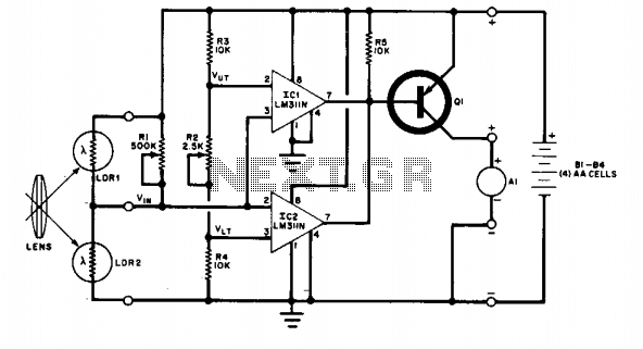
The change in ambient light triggers the alarm by changing the resistance of LDR1 and LDR2. The circuit utilizes two light-dependent resistors (LDR1 and LDR2) to detect variations in ambient light levels. LDRs are passive components that exhibit a change...
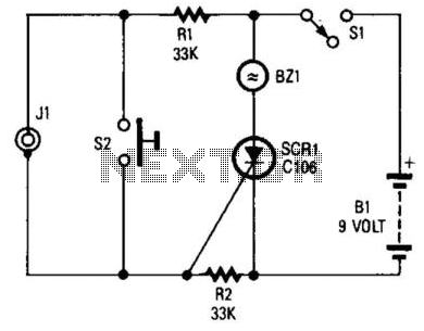
If you choose to create your own moisture sensor, this foil pattern will be useful. A sensor connected to J1 activates CR1, which sounds buzzer BZ1. The sensor consists of a printed circuit board (PCB) foil pattern grid. Multiple...
This is a straightforward 12V rechargeable smart battery charger circuit. It can be utilized as a charger for car batteries, inverter batteries, emergency light batteries, and more. An automatic indicator alarm circuit accompanies this battery charger schematic. The primary...
This circuit cannot be shut off for 10 to 60 seconds, even if the trip condition is immediately removed. It draws no standby power from the battery and is self-resetting. The described circuit operates under a delay mechanism that...
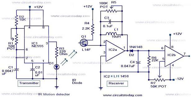
Infrared (IR) Motion Detector Circuit featuring a motion detector alarm and an infrared sensor. The circuit diagram and its operation are provided in detail. The infrared (IR) motion detector circuit is designed to detect motion within a specified range and...
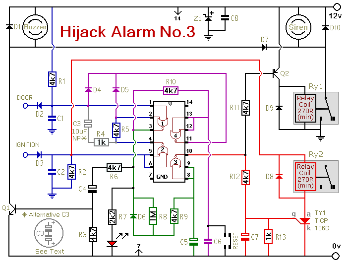
Similar to the initial two Hijack Alarms, this circuit is designed to activate if a door is opened while the ignition is switched on. After a delay of several minutes, allowing the thief to move a safe distance away,...