Ensemble RXTX Builders 2

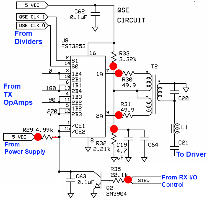
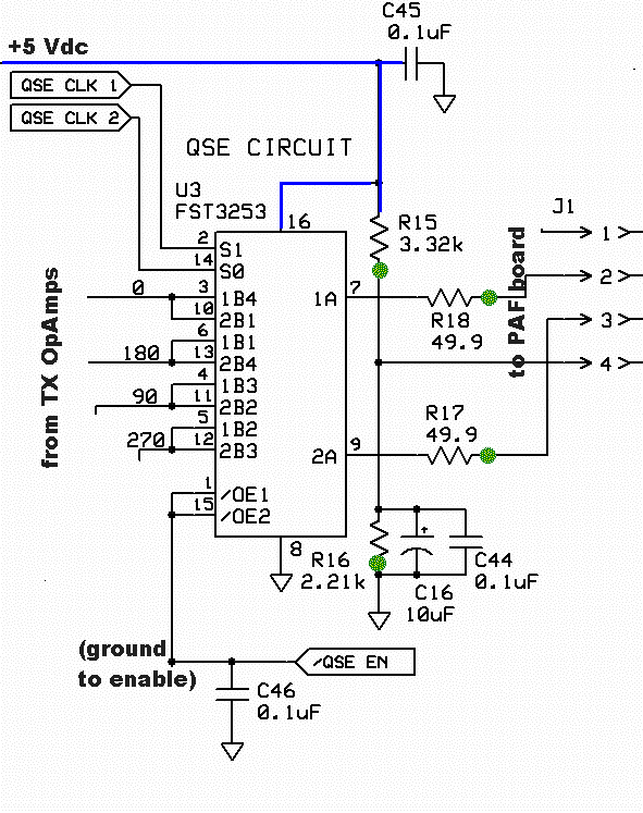
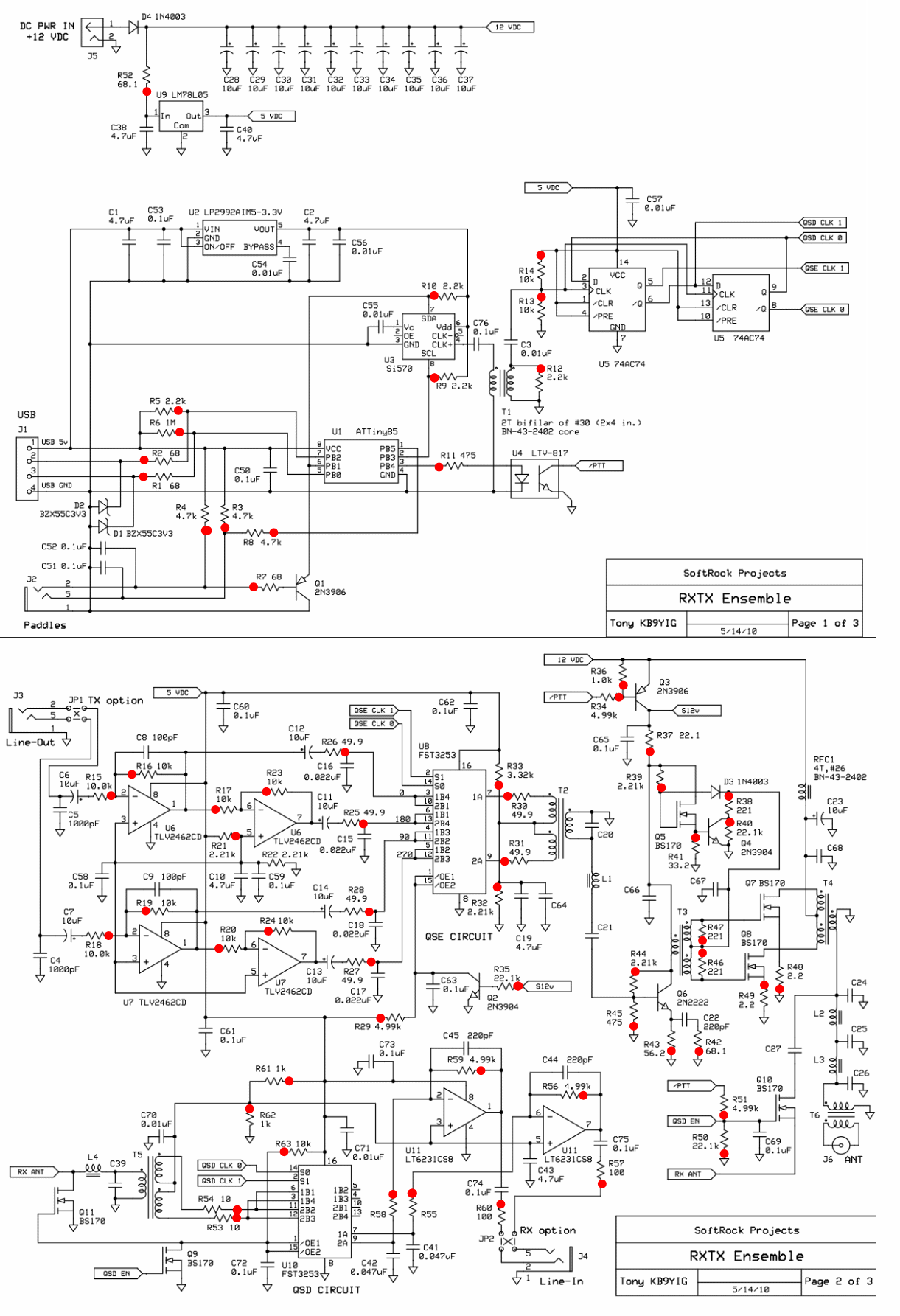
This stage integrates the TX Mixer into the board and facilitates the modulation of the output signals from the Dividers using the four I and Q signals from the TX OpAmps (Quadrature Sampling Exciter - QSE). The result is a double sideband RF waveform that is coupled into the PA Stage. For example, if operating on 40m with an SDR center frequency of 7.056 MHz, and tuning the SDR (via software) to listen to a CW station at 7.066 MHz (10 kHz above the center frequency), listening to the I and Q signals from the hardware RX through an amplifier or headphones (assuming minimal noise) would yield a single 10 kHz CW signal in both channels. The phase difference between the I/Q signals allows the SDR RX software to determine that the signal is 10 kHz higher than the center frequency, displaying the CW signal as a broken line on the waterfall. The software also frequency shifts this signal at the soundcard output so it is heard as a normal CW tone from the speakers. When transmitting at the selected frequency (7.066 MHz), the SDR software emits a 10 kHz signal in both I and Q outputs, again in quadrature. This signal enters the SDR hardware on the TX side, passing through the TX OpAmps and into the TX Mixer, where it interacts with the LO center frequency of 7.056 MHz. The mixer input is a 10 kHz signal from the soundcard; its output is the RF product of the LO and the 10 kHz input signal. This audible tone represents the delta between the center frequency and the desired transmit frequency. Selecting a higher transmit frequency, such as 7.080 MHz, would yield a 24 kHz signal, which may not be audible. However, the TX Mixer will effectively upconvert this to an RF product. The TX OpAmps operate at unity gain and split the incoming I and Q signals into four components: 0, 180, 90, and 270 degrees phase. Each component is input to the TX Mixer, which mixes them with LO signals that are 90 degrees apart in phase. The two mixer outputs are the up-converted RF products, which are in anti-phase (180 degrees apart). These RF products are directed to the Driver/PA Stage through a transformer (T2) that cancels one of the anti-phased RF signals based on which is leading or lagging. Minor phase errors are compensated similarly to the RX stage. The software adjusts the phase and level of the I/Q signals so that the mixing product 10 kHz below 7.056 MHz is cancelled, resulting in a signal 10 kHz above 7.056 MHz at the TX Mixer’s T2 output. The SDR software sends two suitably phased signals from the soundcard; the transmitted signal is an up-converted mixer RF product that is amplified and filtered in the PA board. Note: the above description pertains to the traditional "Softrock/Rocky/Winrad/Genesis fixed center frequency" paradigm. In the PowerSDR paradigm, the process differs slightly. During reception, all versions of PSDR (except the Genesis version) utilize a pseudo IF system, typically set at 9 kHz. Upon transmission, the LO frequency shifts by 9 kHz to align with the desired TX frequency, which has the advantage of maintaining TX image rejection within the same sound card frequency range, typically from DC to about 3 or 4 kHz. Both Rocky and the Genesis PSDR version utilize a fixed LO frequency.
The TX Mixer stage is crucial for converting the low-frequency I/Q signals into higher-frequency RF signals suitable for transmission. The TX OpAmps ensure the proper phase manipulation of the signals, allowing for effective mixing and subsequent RF generation. The use of quadrature signals facilitates efficient modulation, which is essential for maintaining signal integrity and minimizing distortion.
In practical applications, the TX Mixer is designed to handle a range of frequencies, ensuring compatibility with various SDR setups. The output from the TX Mixer is carefully filtered and amplified to meet regulatory standards and ensure optimal performance in real-world conditions. The transformer (T2) plays a critical role in balancing the output signals, allowing for efficient power transfer to the PA Stage while minimizing potential interference.
Overall, this stage exemplifies the integration of digital signal processing with traditional RF techniques, illustrating the evolution of modern SDR systems. The careful design and implementation of the TX Mixer and associated components are essential for achieving high-quality transmission in amateur radio and other communication applications.This stage adds the TX Mixer to the board and provides the modulation of the Dividers` output signals by the 4 I and Q signals from the TX OpAmps (Quadrature Sampling Exciter - QSE). The result is a double sideband RF waveform that will be coupled into the PA Stage. Let`s suppose you were working 40m with a SDR center frequency of 7. 056 MHz. You have tuned your SDR (via the software) so that you are listening to a CW station on 7. 066 MHz (10 kHz up from the center frequency). If you were to listen to the I and Q signals from the hardware RX via an amplifier or headphones (assuming there were no other signals and little noise) you would hear a single 10 kHz CW signal on both channels. Your ears may or may not be able to detect the fact that the tone in one ear is 90 degrees out of phase (I.
e. , In quadrature) with the tone in the other ear. By comparing the phase difference between the I/Q signals the SDR RX software determines that this signal is 10KHz higher than the center frequency and displays the CW signal as a broken line on the waterfall. It also frequency shifts this signal at the output of the soundcard so it is heard at as normal CW tone from the speakers.
Now, assume you decide to transmit on that frequency where you have placed your cursor (7. 066 MHz). Your SDR software will emit a 10 kHz signal (the delta between the center frequency and the selected TX frequency) in both the I and Q outputs, again, in quadrature. This will go into the SDR hardware on the TX side, through the TX OpAmps and into the TX Mixer, where it will beat up against the LO center frequency of 7.
056 MHz. The input to the mixer is 10KHz from the soundcard; the output from the mixer is the RF product of the LO and the input 10 kHz signal. If you were to listen to the input 10 kHz signal you would hear a tone. This tone is audible simply because it represents the delta between the center frequency and the desired transmit frequency, in this case, only 10 kHz, and, since it is in the range of audio frequencies, is audible.
If you were to select a higher frequency on whch to transmit, say 7. 080 MHz, the resultant signal would be a 24 kHz signal; perhaps your dog would hear it, but you certainly would not! However, the TX Mixer will happily upconvert this to an RF product! The TX OpAmps are unity gain and serve to split the incoming I and Q signals into 4 components: 0, 180, 90, and 270 degree phase.
Each of the four are then input to the TX Mixer and are switched ("mixed" by the LO signals which are 90 degrees apart in phase). The two outputs of the mixer are the up-converted RF products, in anti-phase (I. e. , 180 degrees apart). These RF products are fed to the Driver/PA Stage. Via a transformer (T2) that will cancel out one or the other of the anti-phased RF signals out, depending upon which is leading and which is lagging.
This is just like the RX, any minor phase errors are compensated. The software will make the phase and level of the I/Q signals such that the mixing product 10KHz below 7. 056 is cancelled leaving a signal 10KHz above 7. 056 at the output of the TX Mixer`s T2. The SDR software sends two suitably phased signals from the soundcard it is not that tone that is transmitted, but an up-converted mixer RF product, amplified and filtered in the PAF board.
Note: the above description relates to the traditional "Softrock/Rocky/Winrad/Genesis fixed center frequency" paradigm. In the PowerSDR paradigm, things are a little different. On receive, all versions of PSDR (other than the Genesis version) make use of a pseudo IF system, nominally set at 9kHz.
When you go to transmit, the LO frequency is shifted by 9kHz so that it is actually at the wanted TX frequency. That has the distinct advantage that the TX image rejection is always carried out a the same sound card frequency range, i.
e. DC to say 3 or 4kHz. For Rocky and the Genesis PSDR version, both use a `fixed` LO fo 🔗 External reference


