
Ensemble II VHF RX
The circuit design begins with the reception of VHF signals through the antenna, which is connected to the input terminal. The incoming signal is then subjected to a band-pass filter to eliminate unwanted frequencies, ensuring that only the desired VHF band is processed. The pre-amplification stage, implemented with transistor Q1, boosts the signal strength to a suitable level for further processing. The double-balanced mixer (U7) is a critical component in the down-conversion process, where it combines the incoming VHF signal with the local oscillator frequency generated by the Si570 (U3). The choice of 115.2 MHz for the local oscillator is intentional, as it facilitates the desired frequency conversion, resulting in a difference frequency of 28.8 MHz, which falls within the HF range.
The output from the mixer is then filtered to remove the sum frequency, allowing only the difference frequency to pass through. This filtered signal is transformed into two anti-phase signals by transformer T2, which are essential for the subsequent quadrature sampling detection process. The coupling resistors R16 and R17 ensure proper signal integrity as the anti-phase signals are fed into the Ensemble's Quadrature Sampling Detector, which processes the signals for further demodulation and analysis.
The tuning mechanism relies on precise calculations of the local oscillator frequency to ensure that the resulting IF frequency matches the quadrature clock frequency of the SDR system. By employing specific multiplier factors for different bands, the design accommodates a range of VHF frequencies while maintaining operational efficiency. This careful consideration of frequency relationships is crucial for achieving optimal performance in signal detection and processing.
In summary, this circuit design effectively transforms VHF signals into a format suitable for HF processing, utilizing a combination of filtering, amplification, mixing, and detection techniques. The modularity of the kit allows builders to customize their setup based on the desired VHF band, while the thorough documentation and support resources enhance the overall building experience.Replacing the front-end with a circuit that down-converts VHF signals in the 2m, 4m or 6m bands to HF signals that can be received in the RX`s "back-end" (which is essentially the Ensemble II RX). The parts provided in this kit permit the builder to select which of the major VHF bands to implement; all the parts for all the options are included in the kit.
Band-specific parts are identified throughout the documentation; the builder makes his/her choice at build-time. The builder will find invaluable information at the website of Fred PE0FKO, especially the setup of the software and firmware, as documented in the excellent users manual from Bob G8VOI.
This kit reuses a large percentage of the design of the Ensemble II RX (HF/LF) kit. Refer to that kit`s home page for a theory discussion on the radio. This kit reuses the following stages, basically untouched, from the Ensemble II RX: The main difference is in the RF and COntrol stage, which is based upon an earlier design for a VHF add-on board for the Softrock V9. 0 RX. The theory of the Software Designed Radio can be gleaned from the Ensemble II RX documentation. Here, we will concentrate on the differences (where the RF/Auto BPF functionality is replaced with the stage described in the following paragraphs.
This discussion will use, as an example, a 144 MHZ signal that will be down-converted to an IF in the apporpriate HF frequency range for detection in the "standard SDR" stages. The incoming signal from the Antenna terminal (or, via a jumper wire from J1/P100 Pin 1), e. g. , 144MHz, is filtered, then pre-amplified by Q1 and fed to a double-balanced mixer, U7. U7 also receives a Local Oscillator signal via from the Si570`s (U3`s) LO Out. This local oscillator signal must be at a frequency (in our example, 115. 2 MHz) which, when mixed with the incoming 144 MHz signal, will produce both a difference (144 - 115.
2 = 28. 8MHz) and the sum (144 + 115. 2MHz = 259. 2MHz). Fred PE0FKO`s Firmware handles this translation. See notes below on how to program the AVR (U1) to result in an IF frequency that is equal to the Ensemble`s quadrature clock frequency. The output of the mixer at U7`s pin 2 is filtered to remove the sum (image frequency). The (difference) IF is transformed into two anti-phase signals by T2 and fed to the Ensemble`s Quadrature Sampling Detector via T2`s secondaries and the coupling resistors R16 and R17.
At this point, the radio operates pretty much the same way that the HF/LF versions of the Ensemble II RX operate. Tuning the band is then done in the Ensemble VHF RX on signals centering around the quadrature clock frequency (converted in software to the corresponding VHF frequency display values).
Care must be taken to calculate the LO frequencies so as to arrive at an IF that is exactly equal to the quadrature clock frequency. This is done using a multiplier factor that is specific to the band. This multiplier for 2m is 0. 8; for 4m and 6m it is (4/3). For the non-expert builders among us, this site takes you through a stage-by-stage build of the kit. Each stage is self-contained and outlines the steps to build and test the stage. This ensures that you will have a much better chance of success once you reach the last step, since you will have successfully built and tested each preceding stage before moving on to the next stage.
You can review the common construction techniques for induc 🔗 External reference
Related Circuits
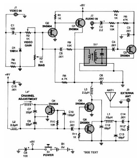
A low-power VHF TV transmitter is an essential tool for video enthusiasts, allowing the transmission of signals from a VCR to any television in a home or backyard setting. This device enables the convenience of watching movies by the...
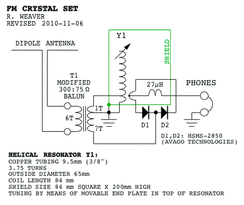
Phase-sensitive detectors typically measure the difference between an input frequency-modulated (FM) signal and the same signal after it has been processed through a resonant circuit or a delay line. A 1N34 diode is suitable for detecting signals at 100...
The circuit was designed to increase an input signal of 4 Watts to 6 Watts, operating within the VHF radio frequency band, specifically for FM transmission. This circuit is engineered to amplify radio frequency signals in the VHF band, which...
VHF overtone crystals can be challenging to utilize due to the multiple frequencies at which the crystal can oscillate effectively. A typical 100 MHz, 5th-overtone crystal may oscillate at approximately 20 MHz, 60 MHz, 100 MHz, and even 140...
This kit is the earlier, now retired Ensemble RX version. These instructions are provided for those who possess and might have delayed building that version of the Ensemble RX kit. The latest version is the Ensemble RX II kit....
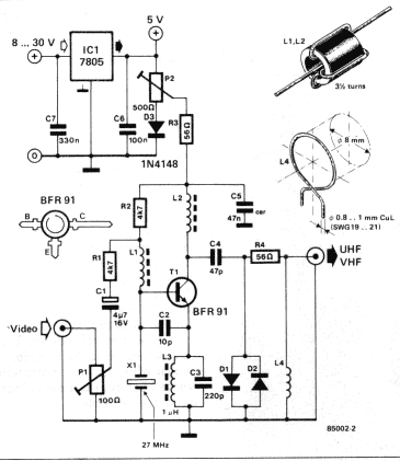
A TV modulator is really no more than a transmitter. It is a very small transmitter, admittedly, but none the less that is what it is. What does a modulator actually do? In general - and this design is...