
Microcontroller Programming 2
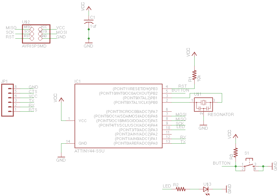
The circuit design involves a microcontroller interfacing with a button and an LED. The microcontroller is programmed to read the button state and control the LED output based on the game's logic. The button is connected to a digital input pin on the microcontroller, while the LED is connected to a digital output pin. A pull-down resistor may be employed to ensure the button input reads low when not pressed, preventing floating states that could lead to erratic behavior.
The microcontroller's firmware includes a routine that initializes the button and LED, setting the appropriate modes for each pin. The main loop of the program continuously checks the button state at a high frequency (1 ms), allowing for immediate response to user interactions. When the button is pressed, the microcontroller generates a random number representing the pattern sequence, which is then converted into a series of LED flashes corresponding to the generated pattern.
The timing for the LED flashes is carefully calibrated to ensure clarity and user engagement. After the LED displays the pattern, the program enters a state where it waits for the user to replicate the sequence. The user’s input is monitored in real-time, and feedback is provided through the LED to indicate success or failure.
The overall design emphasizes user interaction and responsiveness, demonstrating effective programming techniques for handling input and output in microcontroller applications. The lessons learned from the assembly and debugging processes highlight the importance of proper soldering techniques and the use of flux in ensuring reliable electrical connections. The project serves as a practical application of microcontroller programming and circuit design principles.For this week`s assignment we were given a chip design and told to add a button and an LED (i. e. a light). Then we had to actually fabricate the chip and program it to do something with that light and that button. Since this was my first time programming a non-arduino-based microcontroller (and my first time programming an arduino was also just tw
o weeks ago) I decided to stick with using only the one input and the one output rather than trying to incorporate the serial cable. Once I finished designing I went on to mill the board. I managed to squish the extra components onto the existing design rather than expanding the size of the chip.
You can see in the picture that all of the legs of the microprocessor`s copper plates are connected. This is WRONG! I only discovered my error after I finished stuffing everything. This ended up being a wonderful mistake, however, because I learned the best way to remove a chip from a board! To remove a large component from a board, just add more solder! It sounds counterintuitive but by adding more solder you create a thermal mass which gives you time to heat all of the legs at once.
This means you can just melt all the solder and pull the chip off the board in one fell swoop. Once the board was all stuffed I started playing with the programming aspect of it. I quickly learned that my joints still didn`t work, and so I learned my second valuable lesson - Flux makes everything work. By adding flux to each joint and just running the iron by all of the joints I was able to debug the board without having to test any connections.
I decided to create a pattern matching game for my assignment (aka "simon"). When you push the button, the chip generates a random 8-step pattern (i. e. a random number from 0 to 255) and plays the pattern to you by flashing the LED. Then it`s your turn to repeat the pattern exactly. If you get the pattern right it blinks a success pattern (". -. -") and if you miss a beat or press the button too early it blinks a failure pattern (- - - - - - - - -) and you lose the round. The hardest part of the program was figuring out the timing and ensuring responsiveness. At first I had it so you needed to be pressing the button at instantaneous moments (i. e. it would check button state every 200 ms). But this proved to be a very difficult to play because it meant that the button didn`t feel linked to the light (it waited every 200 ms to check, meaning if you pushed or released the button in the middle it wouldn`t affect the state of the light).
I ended up checking the state of the button once every 1 ms and saying that if the button was pressed for more than half the time in a given period, that counted as a button press. This allowed me to light up the button as the user pressed it (i. e. making the game responsive) while also keeping track via a timed counter. 🔗 External reference
Related Circuits
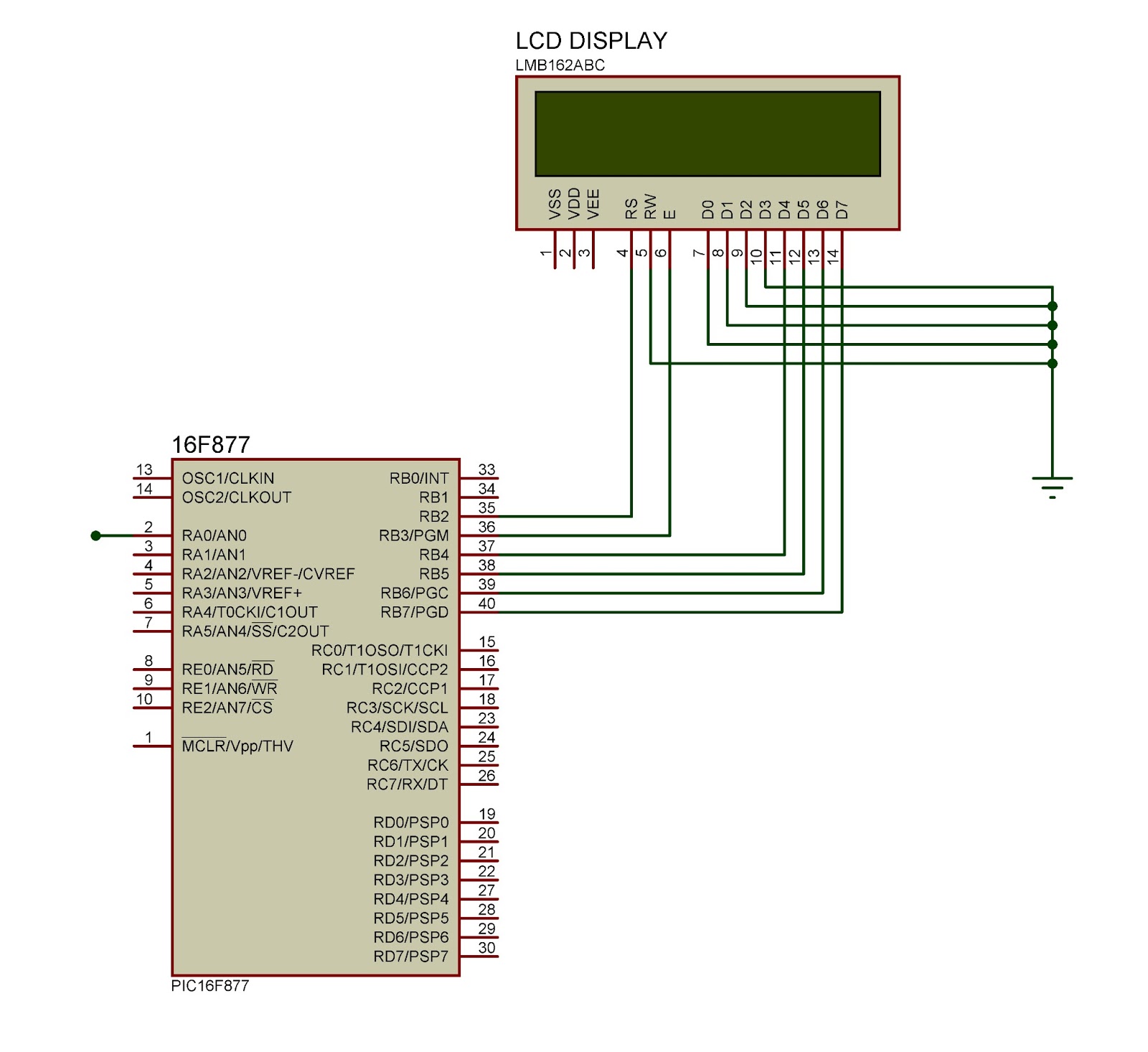
This document outlines the connection of a 16x2 LCD display to a microcontroller, specifically the PIC 16F877A. The circuit diagram is provided, although power supply and oscillator connections for both the PIC and LCD are not depicted. The LCD...
This project automates home appliances via a Bluetooth-enabled PC. A USB Bluetooth adapter is utilized on the PC side, while a Serial Bluetooth module is employed for communication. This project involves the integration of a Bluetooth-enabled PC with home appliances...
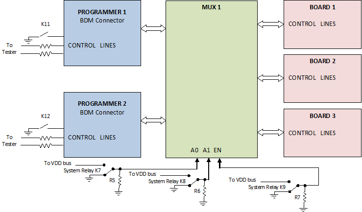
The use of programming pods has become a standard practice in manufacturing, particularly during the early development stages of firmware for new products. Once visual and structural tests are completed, the board is prepared for full functional testing. The...
Standard serial interfacing of a microcontroller (TTL) with a PC or any RS232C standard device requires a TTL to RS232 level converter. A MAX232 is used for this purpose. It provides a 2-channel RS232C port and requires external 10µF...
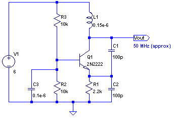
The core of any transmitter is typically an oscillator circuit, and in simple transmitters, such as QRSS devices, a crystal is often used. Frequency adjustment is achieved by modifying the capacitance to ground on one of the crystal's legs....
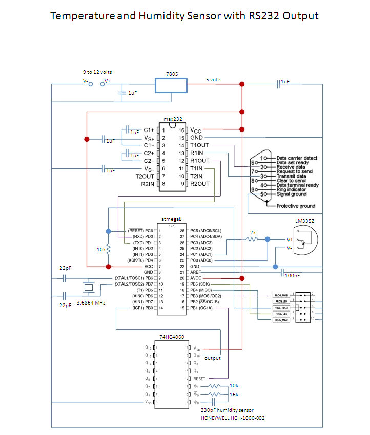
This is an affordable method for measuring temperature and humidity with a computer interface, designed as an entry-level project for high school students on a limited budget. The project involves the integration of a temperature and humidity sensor, such as...