
Error Compensation Circuit for Pressure Sensor
Offset errors in pressure measurement systems can lead to inaccuracies in the readings, which may affect the overall performance of the system. To address this issue, several circuit designs have been developed. Common methods to eliminate offset errors include the use of differential amplifiers, instrumentation amplifiers, and auto-zeroing techniques.
A differential amplifier can be utilized to compare the output of the pressure sensor with a reference voltage. By amplifying only the difference between these two signals, the circuit effectively cancels out any common-mode noise or offset present in both signals. This approach is particularly useful in applications where high precision is required.
Instrumentation amplifiers are another effective solution for offset error correction. These amplifiers provide high input impedance and excellent common-mode rejection, making them ideal for interfacing with pressure sensors. The design typically includes three operational amplifiers, which work together to amplify the difference between the sensor output and a reference voltage while minimizing the impact of offset errors.
Auto-zeroing techniques involve periodically resetting the output of the sensor to a known value, effectively eliminating any offset. This can be achieved through the use of sample-and-hold circuits that capture the output of the sensor during a calibration phase, allowing for real-time correction of offset errors during normal operation.
In summary, various circuit designs are available to eliminate offset errors in pressure measurement systems, including differential amplifiers, instrumentation amplifiers, and auto-zeroing techniques. Each method has its advantages and is selected based on the specific requirements of the application, such as accuracy, noise sensitivity, and ease of implementation.To obtain an accurate pressure value, we must remove the offset errors. There are? many basic circuit designs that is used to remove the offset errors. This. 🔗 External reference
Related Circuits
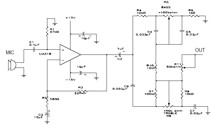
This electronic project is a simple microphone preamplifier based on the LM318 operational amplifier. The LM318 is configured as a standard non-inverting amplifier. Resistor R1 provides a ground reference for the bias current of the non-inverting input. The combination...
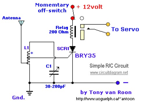
The diagram illustrates a straightforward and efficient receiver designed for activating garage doors, starter motors, alarms, warning systems, and various other applications. The silicon-controlled rectifier (SCR) utilized in this circuit features an exceptionally low trigger current of 30 µA,...
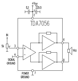
This TDA7056 power audio amplifier circuit diagram project is designed to deliver a maximum output power of 1 watt into an 8-ohm load when powered by a 6-volt supply, or a maximum output power of 3 watts into a...
The NE555 circuit implementation involves various connections and configurations. The circuit is designed with a supply voltage (Vcc) of +11V. The input terminal (pin 3) serves as a reset pin, and the relay and motor components are integrated into...
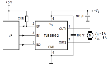
The schematic below illustrates the TLE5206-2 5A H-Bridge circuit for DC motor applications. This device features an integrated power H-bridge with DMOS output stages designed specifically for driving DC motors, as indicated in the datasheet. The TLE5206-2 circuit application...
Switching regulator subsystems intended for use as DC to DC converters. 3V to 40 Volt DC Converter circuit. The use of switching regulators is becoming more pronounced than that of linear regulators because the size reductions in new equipment...