
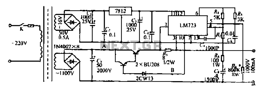
A volt DC power supply circuit
The NE555 timer IC is a versatile component widely used in various applications, including timing, pulse generation, and oscillator functions. The circuit typically operates in either astable or monostable mode, depending on the configuration of external resistors and capacitors connected to the timer.
In the astable mode, the NE555 generates a continuous square wave output, with the frequency and duty cycle determined by the resistor and capacitor values. The output is taken from pin 3, which can drive various loads, such as LEDs, relays, or other electronic devices. The reset functionality on pin 4 allows for interrupting the timer operation, while the threshold and trigger pins (pins 6 and 2, respectively) are used to set the timing intervals.
In the monostable mode, the NE555 produces a single output pulse in response to a trigger signal. The duration of the pulse is determined by the resistor and capacitor connected to the timing pins. This mode is commonly used for applications requiring a timed response, such as in delay circuits or pulse-width modulation.
The power supply for the NE555 circuit is typically provided through pin 8 (Vcc), and it is essential to ensure that the voltage levels are within the specified range for reliable operation. The output pin (pin 3) can source or sink current to drive connected components, making it a critical part of the circuit design.
Overall, the NE555 timer IC is a robust and flexible component that can be adapted for various electronic applications, making it a staple in circuit design for both hobbyists and professionals. Proper understanding of its configuration and operation is crucial for effective implementation in any project. By the old I *, jh;, ililiiit; NE555 circuit implementation and other child member, NE555 1yj complex I end (6) feet. Set bit Vr: {2) feet Ding electrical equipment connected s servant K indole road by J4L/ipi border value +11, etc., the pair of the two ports Ib E just equal to the supply voltage Vcc 1- 2. That is set to catch the f Min quiet 1/3Vt: e, r small reset explain false 2/3Vce. ijc ~ mc to tie Cui il: Huang Zhong like hanging system h1E55 of special planing plant clamor servant.
j: Electric Slap ln], mountain riuh L2 na ashamed River. IC (NE555) WJ (6) feet for the electricity supplier -I. LIj input terminal (3) is also low reset pin diode rely V r Kazuya fI. Relay Pi release like confusion, motor Ml] + rotating chain l-.wj hit l ~ iH travel outside walking XK2 move, throw out a {r XK2 later. XK 2 WJ touch. Closed .1C Wd (2) feet potential Ov, s {j little bit Shua Zha two rubbish] who l/3Vce more t [C Phi Chad (3) feet 1 electric amidine change i/t;., Following.
I-what measures the foundation f contact manifold station, electrical} Jl {sneeze to fil/iJ wire transfer .lU village l ifLiXK2 touch. Zengduanqiongdan. Foot electric complex to l 2vce. when the back (6) feet lu shovel also address door vce, da 1; reset electrical shaving lc - bu, wh ic output terminal (j) i loyal electronic information .h {; sit, machines continue unpredictable rotating .i old block j {sleep stroke .li7r share skewer ge xk1 h soil 1 foot.
goblets journal servant crossed period fiii electric half fi -}, chih dust mountain rrm rotation
Related Circuits
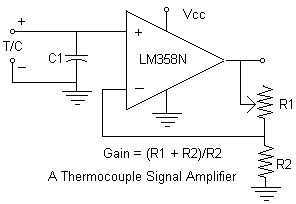
Continuing with the thermocouple interface concept, the next step is to amplify the TC's millivolt signal into a more readable analog voltage, on the order of 0 to 5VDC. This simple circuit fits the bill. The LM358N is a...
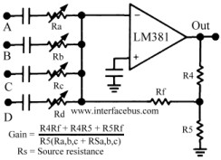
The circuit schematic below represents a method for designing an audio mixer. The active component is an LM318, although any operational amplifier could be used in its place. The circuit is a classic design for an operational amplifier summing...
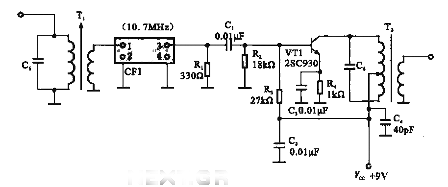
This circuit features a ceramic filter integrated with an FM intermediate frequency (IF) amplifier. The FM IF amplifier circuit primarily consists of an input variable voltage regulator (T), ceramic filters (CF1), and additional components such as the IF amplifier...
Here is a simple circuit which can be used for decoration purposes or as an indicator. Flashing or dancing speed of LEDs can be adjusted and various dancing patterns of lights can be formed. The circuit consists of two...
A new post has been created regarding the Sunrise Word Clock project. The initial attempt to implement the circuit on a breadboard was unsuccessful, likely due to inadequate connections and suboptimal layout choices. The project has been rebuilt with...
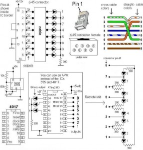
A LAN tester circuit diagram is presented in two designs. The first design utilizes a timer IC 555 and a decade counter 4017. The second design employs a microcontroller ATtiny2313. The first design of the LAN tester circuit incorporates the...