
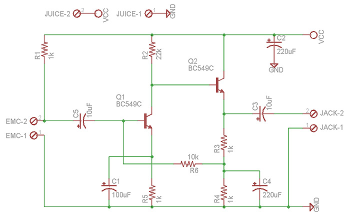
Schematics Stereo Parabolic Microphone

The mini condenser microphone circuit is designed to efficiently convert acoustic signals into electrical signals for various audio applications. The circuit employs a combination of components to ensure high-quality sound capture and amplification. The core of the circuit is the mini condenser microphone, which is supported by the resistor R1 that provides the necessary biasing for the internal amplifier transistor. The 2N3906 PNP transistor serves as a low-noise input amplifier, enhancing the microphone's sensitivity and performance.
For audio signal level adjustment, a 10K gain potentiometer is incorporated, allowing for precise control over the output level. This can be achieved using a stereo 10K audio taper potentiometer for simultaneous adjustments of both channels or individual 10K trimmers for fixed gain configurations. The preamplified output is sent to the 1458 op-amp, which boosts the signal to a level suitable for driving an 8-ohm headphone or a tape recorder input. The 1458 operates in a fixed gain configuration (10X) in the inverting mode, ensuring consistent amplification of the audio signal.
Capacitor C9 plays a critical role by providing DC isolation from the op-amp output, which is biased at half the supply voltage. Resistor R13 serves as an impedance protector, minimizing audio distortion when driving low impedance loads such as headphones. The DC bias for the op-amps is established using a voltage divider formed by resistors R16 and R17, ensuring stable operation of the amplifier stage.
Further filtering of the DC power supply is accomplished through capacitors C13 and C14, which clean the power for the op-amp, while resistor R15 and capacitor C11 filter the input preamp transistors. To safeguard the circuit from reverse battery connections, diode D1 and resistor R18 are included, enhancing the circuit's reliability.
The assembly of the Big-E circuit can be done on a printed circuit board or through hand wiring, with a recommendation for installation in a metal enclosure to mitigate unwanted electromagnetic interference and hum. For applications such as surveillance, the microphones can be strategically mounted for optimal performance. The design provides flexibility in user interface, with volume control accessible via the edge of the enclosure, and audio connections facilitated through 3.5mm mono and stereo jacks.
The innovative use of a parabolic reflector, crafted from an old wok lid, allows for directional sound capture, with microphones positioned at the focal point for maximum efficiency. The overall design emphasizes user safety and comfort, advising gradual volume adjustments and careful handling to prevent discomfort from sudden loud sounds. This circuit is particularly effective for capturing distant sounds, making it suitable for various outdoor listening applications, such as wildlife observation and environmental monitoring.The mini condenser microphone converts sounds into an electrical signal. Resistor R1 provides bias for the condensor microphone`s internal amplifier transistor. The 2N3906 PNP transistor acts as a low noise microphone input amplifier. The 10K gain potentiometer is used for adjusting the audio signal level. A stereo 10K audio taper pot can be used for adjusting both channels simultaneously, or individual 10K trimmers can be used for fixed gain applications. The preamp output signal is fed into the 1458 op-amp, which boosts the audio to a level that is sufficient for driving an 8-ohm headphone or a tape recorder input.
The 1458 amplifier stage is fixed gain (10X) in the inverting configuration, it drives the headphone speakers. Capacitor C9 provides DC isolation from the 1458 op-amp output, which sits at half of the supply voltage.
Resistor R13 provides impedance protection for the op-amp output and reduces audio distortion when driving low impedance headphones. DC bias for the 1458 op-amps is set at half of the supply voltage by the R16/R17 voltage divider. Capacitors C13 and C14 filter the DC power supply for the op-amp stage. The DC is further filtered for the input preamp transistors through resistor R15 and capacitor C11. Diode D1 and resistor R18 protect the circuit from reverse battery polarity. The Big-E circuit can be assembled on a circuit board, or hand wired. The board should be installed in a metal box for shielding from unwanted hum. For surveillance applications, the condenser microphones can be mounted directly on the PC board or on the edge of the metal box.
The volume control can be mounted on the edge of the box, two 3. 5MM mono jacks were used for the microphone inputs, a 3. 5MM stereo jack was used for the headphone output. The 9V battery was mounted inside of the box, power is switched via a switch on the 10K stereo potentiometer. The parabolic microphone assembly was made from an old Chinese wok cooker lid. The microphones are mounted on a metal standoff that places them at the focal point of the parabolic reflector.
Pre-formed computer microphones were used for the model shown. The optimal microphone position can be found by pointing the reflector at a distant audio source, then moving the microphones for the loudest sound. The circuit box was mounted on the back side of the wok lid, it was attached to a piec of 1/2" square aluminum tubing, which forms a handle.
Start with the volume turned down, point the Big-E at a remote sound source, then gradually turn the volume up until the sound is heard. Be careful not to hit the side of the parabolic dish when listening, loud sounds can result. Also, beware that a malicious friend can cause you pain in the ears by talking loudly at the parabolic mic.
It is advisable to wear the headphones partially off of your ears while you get used to the operation of the device. The Big-E is great for listening to birds and distant thunderstorms. It is also possible to hear the rustling of leaves on the top of a distant tree during a breezy day. Close-in wind noise may overpower distant sounds. 🔗 External reference
Related Circuits
Level refers to the relative strength of the signal and is measured in decibels. LINE level sources are much-amplified signals compared to MIC (microphone) level signals. Line level typically ranges from -10 to +4 dBm in strength, while MIC...
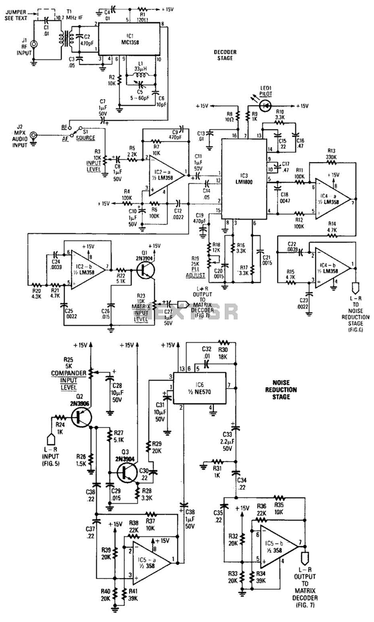
A block diagram of the stereo-TV decoder illustrates the overall relationships between the distinct sections of the circuit, while additional details of each subsection are provided. The decoder section is centered around TCI, a standard 4.5-MHz audio demodulator. The...
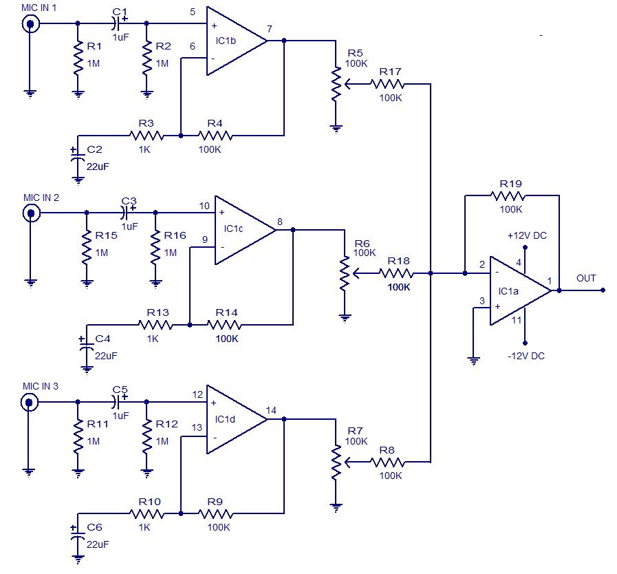
The circuit presented is a three-input microphone mixer and preamplifier utilizing the LM348 integrated circuit. The LM348 is a high-gain, internally compensated quad operational amplifier featuring a class AB output stage. It has a very low input supply current...

This design circuit is for a stereo amplifier intended for a high-sensitivity stereo parabolic microphone, enabling the listening of distant sounds. Unlike typical parabolic microphones that are monophonic, this unit features a stereo audio path, resulting in more realistic...
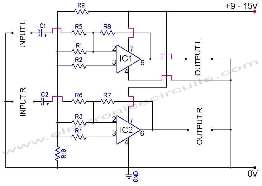
741 Stereo PreAmplifier Circuit Diagram. This preamp circuit provides better than 20dB gain in each channel. PARTS LIST R1 -.. The 741 stereo preamplifier circuit is designed to amplify audio signals with a gain of over 20 dB in each...
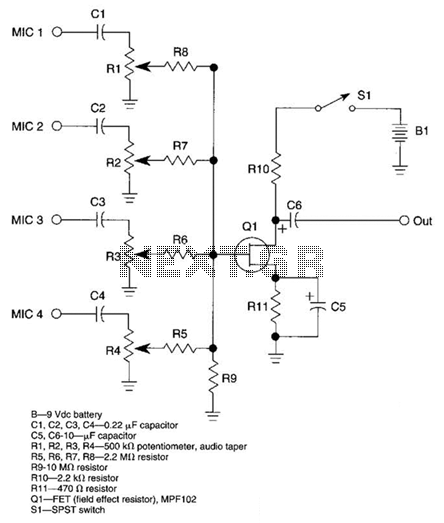
A JFET transistor is utilized as a high-to-low impedance converter and signal mixer. The input impedance is approximately 50.0 kΩ, which can be increased by adjusting resistors R5 to R8 up to 10 MΩ. The output impedance is around...