
ethernet Poor eye diagram where to start looking
The LAN8700 PHY is a critical component in Ethernet communication, responsible for converting digital signals into analog signals and vice versa for transmission over twisted-pair cables. The eye diagram is a crucial diagnostic tool that provides insights into signal integrity by visualizing the timing and voltage levels of the transmitted signal. In this scenario, the PHY has been configured for 100Mbit full-duplex operation, which allows simultaneous transmission and reception of data, enhancing network performance.
The internal 1.8V supply powering the VDD_CORE net is essential for the PHY's operation, ensuring that the internal circuits receive stable voltage levels. The eye diagram's integrity is influenced by various factors, including the quality of the crystal oscillator, the PLL's stability, and the termination of the signal lines. The observed "skewed" transitions in the eye diagram suggest potential timing issues, possibly stemming from the PLL or crystal driver. The PLL's power supply must be stable to ensure accurate frequency generation, while the crystal's specifications must align with the PHY's operational requirements.
The recommendation to remove the 0.01 µF capacitors is based on their potential to introduce unintended impedance or filtering effects that could distort the signal. These capacitors are typically used in non-standard Power over Ethernet (PoE) applications, but standard PoE configurations do not necessitate such components. The design's adherence to standard practices regarding termination and center tap handling is crucial for maintaining signal integrity and minimizing reflections that can lead to eye diagram distortions.
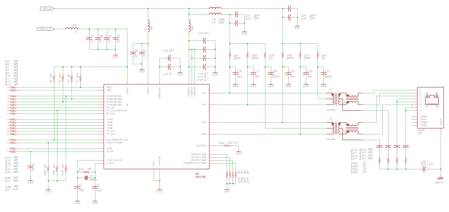
In conclusion, careful analysis of the PHY's configuration, power supply stability, and signal integrity components is essential for troubleshooting the eye diagram issues. Further investigation, including the provision of schematics, will facilitate a more comprehensive understanding of the problem and lead to effective solutions.This is the eye diagram for the transmit pair. The receive pair is very similar. It`s a LAN8700 PHY, and I`ve got the MII interface effectively disabled, so the PHY is transmitting IDLE code sequences. It`s forced into 100Mbit/FDX as per the datasheet. 100Mbit/HDX is identical. Correction: The design is using the LAN8700`s internal 1. 8V supply to power its VDD_CORE net; I must have been confusing the 1. 8V logic supply with the VDD_CORE supply in my earlier description. It seems to me that power supply noise is not such a high likelihood, since the high, zero and low levels are actually pretty decent. That is, the eye isn`t "squished. " The fact that the violations all look like very good transitions, just "skewed" in time makes me think the problem lies in the crystal or supply for the crystal driver/PLL in the PHY.
If I let the eye diagram run (about 15min) the violations in the mask "fill in" such that the white violations you see in the picture become white chevron (>) shapes in the right-hand sides of the blue masks. This would tell me that the timing errors are more or less randomly distributed rather than some kind of discrete noise yanking the timing off an exact amount.
The crystal that the PHY is using has a 30ppm spec which is well within the 100ppm 802. 3 spec, and even within the 50ppm recommended spec that the PHY specifies. I`m using loading capacitors which match what the crystal is looking for, and is pretty close to what the LAN8700 specifies as its nominal capacitance. Before I disabled the MII interface I would see framing errors (as reported my Linux`s ifconfig program).
There are no errors if I force the link to 10Mbit. One of the very odd things I have noticed is that if I set the scope up to trigger on the RX_ER (receive error) signal from the PHY to the MAC, it never signals an error even though the frame errors accumulate in the MAC reports. Now from reading the datasheet for the PHY, it is clear that there are actually very few situations where RX_ER would assert, but I find it very difficult to believe that with an eye diagram like what I am seeing the errors are actually between the PHY and the MAC.
I do understand the basics of eye diagrams, but I`m looking to some of the more experienced posters, hoping that they would be able to share some of their experiences in translating specific eye pattern mask violations to likely sources. I`m using the ethernet conformance test application software on the scope. I tested the conformance test app against a dev board which passes with flying colours. akohlsmith Jan 4 `12 at 0:30 I`d need schematics to say anything for certain. My suspects, at the moment, are: PLL power supplies, XTAL issues, termination, and not handling the transformer center taps correctly.
In that order. With schematics I could narrow some of that down. user3624 Jan 4 `12 at 1:04 It "smells funny" to me that the center tap of one transformer is tied to the same inductor-isolated supply that terminates the signal lines from the other transformer. And vice versa. But I haven`t done any ethernet work like this before, so I don`t know that`s not exactly what you`re supposed to do.
The Photon Jan 4 `12 at 6:13 I see many things that could potentially cause the eye diagram issues that you see. No "smoking gun", but some things that could potentially mess things up. You have 0. 01 uF caps (C211, C212, C214, & C217) on the unused pins of the RJ-45 and the center taps of the transformer.
I recommend shorting out those caps. Your use of caps here is unusual and could cause issues later on, although they are unlikely to be causing the eye-diagram issues you`re having. Near as I can tell, the only reason to have these caps is as a DC-Blocking scheme for when someone is using a non-standard power over Ethernet scheme.
Standard POE doesn`t need this protection, and since the POE standard is now "old" you are unlikely to encounter non-PO 🔗 External reference
Related Circuits
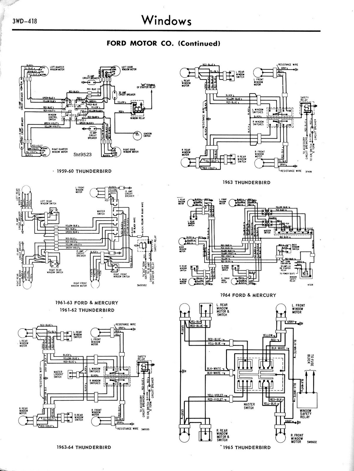
Toyota MR2 Exterior Lights Wiring Diagram Manual PDF Download. The Toyota MR2 Exterior Lights Wiring Diagram Manual provides a comprehensive guide for understanding the wiring configurations associated with the exterior lighting system of the Toyota MR2 model. This manual is...
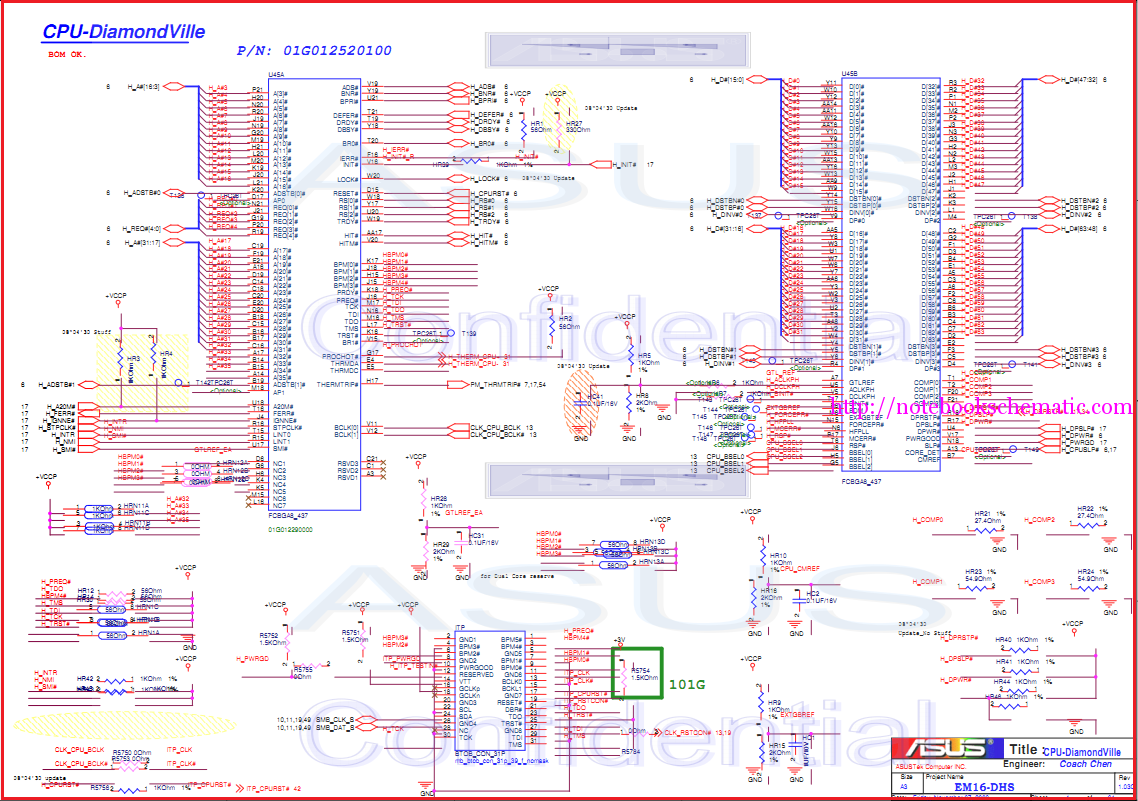
Laptop schematic circuit diagram for laptop repair and laptop BIOS password removal. The laptop schematic circuit diagram serves as a crucial resource for technicians and engineers involved in laptop repair and maintenance. This diagram provides a detailed representation of the...
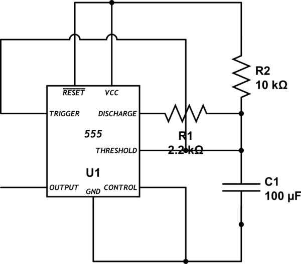
Bold lines indicate soldered connections, while arrows represent wire-based connections. Red indicates V_cc, black represents ground, blue signifies intermediate connections, and gold denotes the primary output. Pins 1 and 5 are connected to ground. It is noted that pin...
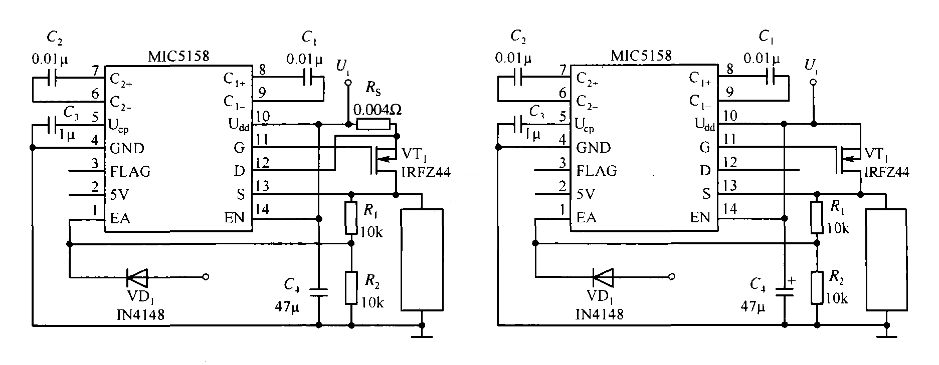
The MIC5158 is part of a high-speed switching circuit diagram that focuses on the rising edge. The MIC5158 is a precision voltage reference and high-speed switching device that is commonly utilized in various electronic applications requiring rapid signal transitions. In...
The automatic sprinkler controller circuit consists of a +12 V power supply circuit, a light control circuit, and an irrigation control circuit, as illustrated in the accompanying figure. The +12 V power supply circuit includes a knife switch (Q),...
The DR-650 wiring diagram pertains to the Suzuki DR-650, a single-cylinder, dual-sport motorcycle. This wiring diagram includes a color code for the wires. The schematic diagram provides complete connections for various components, such as the speedometer, lights, CDI unit,...